Download
1 / 20
200 likes | 286 Views
13-LAN, packets, frames and topologies. Dr. John Abraham Professor UTPA. What happens in data transfer?. For example an email message Information Data (alpha numeric characters) DataSegment SegmentPacket PacketFrame FrameBits. Headers added.

E N D
13-LAN, packets, frames and topologies Dr. John Abraham Professor UTPA
What happens in data transfer? • For example an email message • InformationData (alpha numeric characters) • DataSegment • SegmentPacket • PacketFrame • FrameBits
Headers added • Data (including application header, presentation header, and session header) • Segment Header – Data • Network Header – Segment Header – Data • Frame Header-Network Header- Segment Header – Data – Frame Trailer
Circuit switching • Connection mechanism that establishes a path between a sender and receiver, with guaranteed separation from other paths. Originally used electromechanical switching devices to make a physical circuit. • Today use electronic devices to establish circuits, and multiple circuits are multiplexed over shared media. Three general properties to define a circuit switched paradigm: • Point-to-point communication • Separate steps for circuit creation, use and termination • Performance equivalent to an isolated physical path.
Packet Switching • Basis of internet • Sender must divide the message into blocks of data called packets. • The size of a packet varies depending on the packet switching technology used. • Uses statistical multiplexing • Communication from multiple sources competes for the use of a shared wire. • 3 properties of a packet switched paradigm • Arbitrary, asynchronous communication • No set-up required before communication starts • Performance varies due to statistical multiplexing.
Standards for Packet Format and Identification • LAN – IEEE project 802 • There may be sublayers, eg. Datalink layer is dived into LLC-logical link control (upper portion) and MAC –media access control (lower portion) • Some 802 projects: • 802.3 Ethernet 802.4 Token bus, 802.5 Token Ring. 802.11 wirless. 802.15 bluetooth
LAN topologies • Bus • Ring • Star • Mesh • Advantages and disadvantages
Packet Identification, demultiplexing, mac addresses • Only intended recipient should process the packet. Demultiplexing requires an address. Each computer has a unique address (MAC address) and each packet contains the address of this computer. • 48 bit address on NIC. 3 bytes (MSB) identify the manufacturer (Unique ID, OUI). Remaining 3 bytes is the number for each card.
Types of MAC addresses • Unicast – uniquely identifies a single computer, only that computer get the packet. A source address is always unicast.The lease significant bit of the first byte defines the type of address. If the bit is 0, it is unicast, otherwise multicast. • Broadcast – each computer on that network should receive a copy of the packet. All 48 bits are 1s. • Multicast – identifies a subnet of computers on a given network and all computers in the subnet will receive the packet.
Examples: • 4A:30:10:21:10:1A – lsb of first byte is 0 so unicast. 0100 (4) 1010 (A) • 47:20:1B:2E:08:EE – lsb is 1 so multicast. 0111 (7) • FF:FF:FF:FF:FF:FF – muticast
Broadcast, Multicast and efficient multi-point delivery • LAN transmits over a shared medium. All can hear, each machine should examine the address to determine if it belongs self, or discard the packet. See p.233 for algorithm. • In case of broadcast or multicast only a single copy needs to be transmitted.
Frames and Framing • Framing refers to the structure added to the sequence of bits or bytes that allows a send and receiver to agree on the exact format of the message. • A frame header contains information used to process the frame. • In a ethernet packet switched network a frame has the same data length (payload) as a packet. • An ethernet frame contains seven fields: preamble, SFD, DA, SA, length or type of data unit, upper-layer data and the CRC.
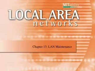
Figure 3.3Ethernet layers TCP/IP Protocol Suite
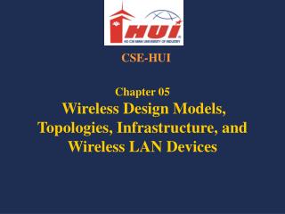
Figure 3.4Ethernet frame TCP/IP Protocol Suite
Frame • Preamble 7bytes alerts the receiving system to the coming frame and enables it to synchronize. • SFD – start frame delimiter. 1byte. Signals the beginning of the frame. • DA/SA – destination and source address. 6bytes each. • Length/type – 2 bytes. number of bytes n the data field. • CRC – 4 bytes. • Must have DA(6), SA(6), Length(2) Data.. And CRC(4), 18 bytes plus data. • Data – encapsulated data from upper layers. minimum of 46 bites and maximum of 1500 bytes. So minumum length of the frame is 64 byte and maximum is 1518 bytes.
802.3 Frame • A SNAP header (8bytes) is added (3bytes LLC, 3byte OUI and 2byte type/length) • LLC = Logical Link control • OUI = Organization unique identifier • This reduced the maximum payload of 1500 to 1492.
Frame • In order to provide service to the network layer, the data link layer must use the service provided to it by the Physical layer. The physical layer only accept a raw bit stream. For a long bit stream, if error occurred during transmission, the entire stream has to be sent again. Therefore, it is broken to smaller frames. Each frame will have to be distinguished somehow. Three methods are used • Character count • Starting and ending characters, with character stuffing • Starting and ending flags, with bit stuffing
Character count The first byte indicates how many characters are in the frame including the first byte. Trouble with this scheme is that if the first byte of any frame gets corrupted, the destination will get out of sequence, having no way to find where the beginning of the next frame is. This method is rarely used any more.
Start and end with control chars with character stuffing Resynchronize at the beginning of each frame Start with ASCII chars DLE & STX Data Link Escape, Start of Text End with the same sequence If these ASCII char is part of the text then double it like Jim’’s book - in pascal Problem - must use 8 bit ASCII which is not suitable for all communications
Start and end with flags with stuffing Each frame begins with bit pattern 01111110 If senders data has five consecutive ones then stuff it with a zero which is deleted at the receiving end This bit pattern called flag byte is added at the end of each frame as well With this method boundary between two frames are easily recognized.