Download
1 / 23
240 likes | 421 Views
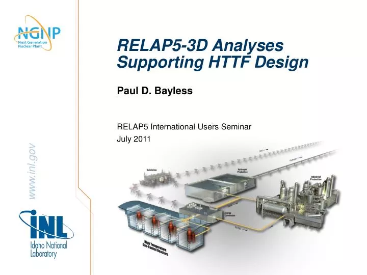
RELAP5-3D Analyses Supporting HTTF Design. Paul D. Bayless. RELAP5 International Users Seminar July 2011. Outline. HTTF description Recent analyses Code user observations. High Temperature Test Facility (HTTF). Integral experiment being built at Oregon State University

E N D
RELAP5-3D Analyses Supporting HTTF Design Paul D. Bayless RELAP5 International Users Seminar July 2011
Outline • HTTF description • Recent analyses • Code user observations
High Temperature Test Facility (HTTF) • Integral experiment being built at Oregon State University • Electrically-heated, scaled model of a high temperature gas reactor • Reference is the MHTGR (prismatic blocks) • Large ceramic block representing core and reflectors • ¼ length scale • Prototypic coolant inlet (259°C) and outlet (687°C) temperatures • Less than scaled power • Maximum pressure of ~700 kPa • Primary focus is on depressurized conduction cooldown transient
HTTF Analysis Overview • Objectives • Determine how well the High Temperature Test Facility (HTTF) will serve as a code assessment data source for validating computer codes that will be used in licensing the NGNP • Identify differences/distortions in the experiment facility design and response and evaluate their significance to code assessment • Approach • Develop and use models of the Modular High-Temperature Gas-cooled Reactor (MHTGR) to determine the steady state and transient response of the reference plant • Develop and use models of the HTTF to determine the steady state and transient response of the experiment facility
Focus of Recent Analyses • Steady state behavior of the core • Assessing impact of operational distortions • Trying to design around distortions • Design simplification • Core design has been a moving target
HTTF RELAP5-3D Model Description • Three systems • Primary coolant • Reactor cavity • Reactor cavity cooling system • Central and side reflector regions divided into regions with or without coolant holes • 2-D (radial/axial) conduction in all vertical heat structures • Heater block unit cell centered on the coolant channel • Radial conduction and radiation inside core barrel • Radiation from core barrel to vessel to RCCS • Coolant risers and dead volume between core barrel and vessel • Core barrel divided azimuthally
Modeling Assumptions • All coolant holes are open at both ends without flow restrictions • Loss coefficients adjusted to provide 11% core bypass flow • 1-mm gap on either side of permanent reflector, but open to flow only at the bottom • RCCS response estimated by applying constant temperature boundary condition to the back side of the panels • Radiation is purely radial from the core to the RCCS • Radiation from top reflector to upper plenum shield is not modeled
Reactor Vessel Nodalization 120 125 132 140, 162 164, 145, 166 150 115 105 200 170 255 250 295 175 100 110
HTTF RELAP5-3D core region radial nodalization (1) Reactor vessel Core barrel Permanent reflector Side reflector Coolant channels Core region Central reflector Heater rod Coolant hole Coolant gaps
HTTF RELAP5-3D Model Unit Cells Reflector Core Coolant channel Heater rod Ceramic Radiation
The Reflectors Are Too Hot • Problem: steady state calculations showed that there were significant hot spots around the heater rods on the core periphery. • Solution: add more coolant holes, so that each heater rod has six coolant holes around it. • Additional change: since the control rod holes were no longer needed for cooling the core, they were moved farther away from the heater rods to simulate the core bypass flow paths, and more were added. The permanent side reflector was also merged with the side reflector.
HTTF RELAP5-3D Core Region Radial Nodalization (2) Reactor vessel Core barrel Permanent reflector Side reflector Coolant channels Core region Central reflector Coolant gap Heater rod Coolant hole
Design Change Effect on Reflector Temperatures Axial Average Temperature (°C)
The Core Periphery Helium Is Too Cold • Problem: the coolant channels on the core periphery have less heat input, so the core outlet temperature varies significantly across the core. • Solution: either add inlet orifices to reduce the flow or reduce the channel diameter. • Inlet orifices are sized for turbulent flow during steady state, but will operate in laminar flow during most transients. Required loss coefficients are high. Removing orifices simplifies operation and modeling, although it removes some flexibility. • Three different core coolant channel diameters are required. How are these combined in a lumped channel model? • Additional changes: the permanent side reflector was separated back out from the side reflector, the number of coolant risers was reduced and their width increased.
Sensitivity Calculations for Reflector Hole Sizes • Calculations run without orifices to determine bypass flow vs. hole size • Target is around nominal bypass flow of 11%.
HTTF RELAP5-3D Core Region Radial Nodalization (3) Reactor vessel Core barrel Permanent reflector Side reflector Coolant channels Core region Central reflector Coolant gaps Heater rod Coolant hole
Core Region Modeling • Two core regions have combinations of three different coolant channel diameters • Need to model these as a single flow channel • Approach • Model the three size channels explicitly • Assign 1/6 heater to each channel that sees 1 heater rod • Assign 1/3 heater to each channel that sees 2 heater rods • Assign 1/2 heater to each channel that sees 3 heater rods • Determine the flow that provides a desired outlet temperature • Model a single channel with the correct total flow area and heat input • Specify the same flow rate determined above • Iterate on the hydraulic diameter to get the same pressure drop
User Observations on the 2-D Conduction Model • Can simplify or eliminate conduction enclosures • It is a specific application of the reflood model • Each axial node divided in two • User cannot control the axial meshing • Cannot be used with a heat flux boundary condition • Cannot be used without a boundary volume • Uses the length of the right boundary volume as the structure height • Can distort the axial conduction if more than one axial structure is attached to the same fluid volume • Can distort the axial temperatures if the user chooses to divide a large, well-mixed volume into a 1-D stack of cells