Download
1 / 44
610 likes | 1.19k Views
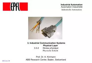
Mechatronic and Industrial Automation. By: Reza Abrishambaf PhD Candidate. Mechatronic & Industrial Automation. Mechatronic : is a multidisciplinary engineering system design is a combination of: Mechanical engineering Electronic engineering Computer engineering Control engineering

E N D
Mechatronic and Industrial Automation By: Reza Abrishambaf PhD Candidate
Mechatronic & Industrial Automation • Mechatronic : is a multidisciplinary engineering system design is a combination of: • Mechanical engineering • Electronic engineering • Computer engineering • Control engineering • Systems Design engineering
Mechatronic & Industrial Automation • French standard NF E 01-010: “approach aiming at the synergistic integration of mechanics, electronics, control theory, and computer science within product design and manufacturing, in order to improve and/or optimize its functionality".
Mechatronic & Industrial Automation • Machine vision • Automation and robotics • Servo-mechanics • Sensing and control systems • Automotive engineering, automotive equipment in the design of subsystems such as anti-lock braking systems • Computer-machine controls, such as computer driven machines like IE CNC milling machines • Expert systems • Industrial goods • Consumer products • Mechatronics systems
Mechatronic & Industrial Automation • Medical Mechatronics, medical imaging systems • Structural dynamic systems • Transportation and vehicular systems • Mechatronics as the new language of the automobile • Diagnostic, reliability, and control system techniques • Computer aided and integrated manufacturing systems • Computer-aided design • Engineering and manufacturing systems • Packaging
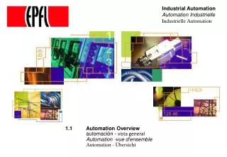
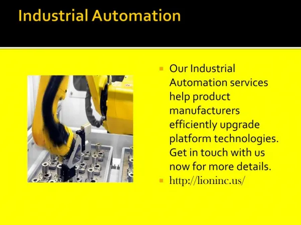
Mechatronic & Industrial Automation • Industrial Automation: “Automation is the use of control systems and information technologies to reduce the need for human work in the production of goods and services”
Mechatronic & Industrial Automation • Advantages and disadvantages The main advantages of automation are: • Replacing human operators in tasks that involve hard physical or monotonous work • Replacing humans in tasks done in dangerous environments (i.e. fire, space, volcanoes, nuclear facilities, underwater, etc.) • Performing tasks that are beyond human capabilities of size, weight, speed, endurance, etc • Economy improvement
Mechatronic & Industrial Automation • The main disadvantages of automation are: • Technology limits • Unpredictable development costs • High initial cost
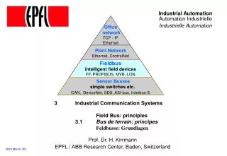
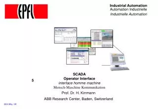
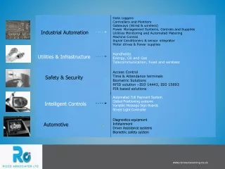
Mechatronic & Industrial Automation • Different types of automation tools exist: • ANN - Artificial neural network • DCS - Distributed Control System • HMI - Human Machine Interface • SCADA - Supervisory Control and Data Acquisition • PLC - Programmable Logic Controller • PAC - Programmable automation controller • Instrumentation • Motion control • Robotics
Mechatronic & Industrial Automation • Industrial Automation main components: • Control Room • Monitoring Room • PLC Room • Shop Floor • Robots • Automated Guided Vehicle (AGV) • Conveyors • Sensor & Actuators
Mechatronic & Industrial Automation • Monitoring Room:
Mechatronic & Industrial Automation • PLC Room:
Mechatronic & Industrial Automation • Shop Floor:
Mechatronic & Industrial Automation • Industrial Robots:
Mechatronic & Industrial Automation • Automated Guided Vehicles (AGV):
Mechatronic & Industrial Automation • Sensors:
Mechatronic & Industrial Automation • Actuators:
Mechatronic & Industrial Automation Useful Courses: • Mechanical engineering and materials science subjects • Electronic engineering subjects • Computer engineering subjects • Computer science subjects • Systems and control engineering subjects • Optomechanics (optical engineering) subjects • Robotics subjects Are you interested in Mechatronic?
An outline for Mechanical Engineering CAD/CAM laboratory Integrated System
Introduction Location: CAD/CAM Laboratory in Mechanical Engineering Department Concept : A flexible manufacturing system including different cells Components:
How does it work? ROBOTS First 5 axis robot is in charge of picking and placing parts which are scanned by the barcode reader, and transfer them to the left side for machining or throw it to the conveyor for the other operations.This robot utilizes a vacuum gripper to pick the parts. Pneumatic Robot which contained a few reed sensors, used to set the limits for the pneumatic cylinder motion. This robot is using a general griper which can be close or open in each time. This robot just picks the parts which are detected by the Metal Detector sensor, placed before it.Hence, the duty of this robot is to pick the Metal-Coated parts, chosen by the sensor placed near it. Second Five axis robot which has the same specifications as the former one, used to pick the Non-Metal parts (which are detected by non-metal detector sensor on the big conveyor) from the flexible conveyor and place them into a rail way for the next defined operations.This robot placed on a special Nut and Screw system which is connected to a Motor using to turning the screw in case of moving the robot across the Big conveyor .
First robot second robot pneumatic robot
COMPUTERS AND SOFTWARES First Robot is controlled by a General PC, using a visual basic program to read the barcodes and also control the robot’s motion. For each part the program decide Where to be placed according to the parts’ barcode The second 5-axis robot is controlled by a PC using special software which is named “Robotica”.Generally, this software has a GIU (Graphical User Interface) which can be used for programming the robot remotely. After writing the program, by pressing the Run Button on the program screen, each line transferred to the robot using a general RS-232 cable. Also we have another PC which is used to monitor the Main PlC , placed in an anti dust cabin for safety.
63Cm 176Cm 11Cm 97Cm CONVEYORS We have 2 Conveyors, one general belt conveyor and one big flexible conveyor which are driven by two different Motors . The specifications of these two conveyors are as below:
PLCs We have two different PLC devices : A Siemens S7-200 PLC with 5 inputs and 5 outputs , which is used as secondary plc device , just to transfer the fire signal to the second five axis robot. A Telemeqanic PLC with inputs and output , used as main PLC device for controlling the motors, conveyors, sensors and all other feedback signals. Telemeqanic Micro TSX PLC SIEMENS S7-200 PLC
REVIEWING THE SCENARIO To run the system three parts are designed for three different operations. At the first cell the scenario is collaboration of the barcode reader and the first robot. After inserting the part in the input place , the small conveyor start switch pushed down and the small conveyor runs.After this the parts moves across the barcode reader for reading the parts’ barcode, after that the conveyor stopped when the part reached the optical sensor on the belt conveyor. The Barcode reader Device 3 parts(1 Metal and 2 Non-metal with different barcodes)
Regarding to the parts’ barcode, two different operations may have done. Parts with barcode going to the box 1, other parts must thrown to the second flexible conveyors , these parts including metal and non-metal parts. Throwing parts into the flexible conveyor, they switch the optical sensor on which caused the big conveyor to turn on. After a while the parts reach the metal detector sensor, in this case if the part was non-metal, it passes the sensor and continue it rout, otherwise the metal detector sensor send a signal to the main PLC and main PLC send signal to the pneumatic robot to catch the metal part.
The non-metal parts continue their route until they reach the non-metal sensor, at this time, the sensor send a signal to the main PLC and the main PLC send the required signal to the robot and also to the screw motion control, so the screw starts turning and the robot get close to the part which is in the conveyor waiting to be caught by the robot. During this operation, the PC which is used to control the second robot must be run and ready to send the program to the robot.The robot catches the part and after that the signal from the non-metal sensor goes off, so the screw starts in reverse direction by receiving a signal from the main PLC , and the robot throws the parts into a special rail at the end of the rout. Non-Metal Detector Sensor Metal Detector Sensor
It must be considered that by detection of any part (metal or non-metal) by the special sensors the big conveyor stopped and waiting for part-received signal from the first sensor of big conveyor.Beside this an alarm system designed to warn the operator if the part is going to reach the sensor in improper position (if it stands vertically) . When the alarm optical sensor detected the part which stood vertically the alarm beep starts and warn the operator to correct the part situation(it must lays on the width of the part) and after that push start button for resuming the conveyor cycle.
How are the Robots Programmed In this integrated system robots are programmed with visual basics. But first coordinates are defined with the help of ROBOTICA. ROBOTICA is a program to define the coordinates for a robot. Each robot has several axes which are controlled with this program.
For example here 3 programmers are written for the robot next to conveyor 2 to take the part to machine 1 or machine 2 or conveyor 1 This command jumps to line one
In the previous slide J stands for jump, M 1,2,.. Are for different axes of the robot and the coordinated for each axis is defined. In order to have a loop in this system J 100 is used to jump the last line to the first line. T stand for time. The robot will wait in a position for a small time interval defined by T 100,200,.. . S and P are used to get a part and release it at specified position.
With the help of these coordinates the visual basic program is written. It is defined in this program for example for a part with a specific bar code, take the part and place it in machine one. Here an outline of the program is given. By selecting any bottom one can change the program
Now three positions are defined for the robot to move to that position, take the part and place it in a machine or conveyor one. Here the codes to place the part in machine one are shown. These codes can be accessed easily by double clicking on box 1 in the program and change the coordinates according to the coordinates that were set in ROBOTICA.
Here are the coordinates for box 2 or machine 2 are shown. One can simply define his/her coordinates according to those he/she defined in ROBOTICA.
Now the coordinates for the conveyor are defined in the program.
I mentioned that a part is placed in machine 1 or machine 2 or conveyor 1 according to its bar code. In this part of the program it is defined how each part is placed according to its bar code. The bar code for each object defines its color and for each color a series of codes similar to the tree potions mentioned are written. Here for example the position for an object with yellow or green color is defined.
There are also a set of codes written for parts which are not in any categories.