Download
1 / 10
100 likes | 201 Views
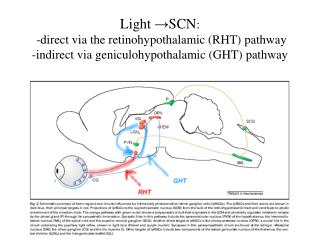
Some features of V1495. Shiuan-Hal ,Shiu Everything in this document is not final decision!. V1495. trigger supervisor. level shifter. y h o d o s c o p e. x h o d o s c o p e. (“times 4”). level 2 v1495. TRIGGER. μ. level 1 v1495. level 1 v1495. level 1

E N D
Some features of V1495 Shiuan-Hal ,Shiu Everything in this document is not final decision!
V1495 trigger supervisor level shifter y h o d o s c o p e x h o d o s c o p e (“times 4”) level 2 v1495 TRIGGER μ level 1 v1495 level 1 v1495 level 1 v1495 level 1 v1495 discriminator We are using 5 v1495 to form into trigger decision system. Each Lv1 v1495 will send 32 bits data to Lv2 v1495. 4 Lv1 v1495s will handle in upper Y’s, upper X’s, lower Y’s, lower X’s
The I/O of V1495 • Lv1 v1495: 3 ECL/LVDS input ports, 1 LVDS output port and 1 ECL output port. Each port have 32 channels • Lv2 v1495: 4 ECL/LVDS input ports, 1 LVDS output port and 1 ECL output port. Each port have 32 channels • All Lv1 LVDS output ports are defined to send data to Lv2 v1495. ECL output data will send to latch card.
FPGA block diagram 40MHz Local clock PLL 250MHz 250MHz/4 Phases Look Up Table (pipeline mode) Data input Sampling unit 1 retiming memory Multiplexer Sampling unit 2 Sampling unit 3 Lv1 512*9*8*3 Lv2 512*9*8*4 Sampling unit 4 One channel Lv1 x96 Lv2 x128 Delay &internal pulse width control Data output The block diagram here only shows the main function for trigger establishing.
Internal pulse structure • After FPGA sampling the input signal edge transition, all the timing information of input signal will be retiming first then stored into the memory in FPGA. • Then we can adjust the signal delay and pulse width before the signal go into the Look up table part. delay AdjustablePulse width
Why we need adjustable delay? • The main purpose of adjustable delay is to avoid using bunch of cable to delay signal and eliminate the different hardware delay in different ports. • We need make sure all the signals go into the look up table part at the same time.
Timing information • Without any look up tables, signals from v1495 input to output cost 82ns. • All the logic in look up tables are going to several steps pipeline process to determine the data pattern. • Each steps cost 4ns, and a typical logic need using 5 steps which need about 20ns to process. • 1 v1495 will cost total 82+(# of step)*4 ns
What is pipeline step Data input Data output Stage1 LUT Stage2 LUT Stage3 LUT Stage4 LUT Stage5 LUT CLOCK if(F_temp_lv1_0( 0)='1' OR F_temp_lv1_0( 1)='1' OR F_temp_lv1_0( 2)='1' OR F_temp_lv1_0( 3)='1')then F_temp_lv2_0( 0)<='1'; else F_temp_lv2_0( 0)<='0'; end if; if(F_temp_lv1_0( 4)='1' OR F_temp_lv1_0( 5)='1' OR F_temp_lv1_0( 6)='1' OR F_temp_lv1_0( 7)='1')then F_temp_lv2_0( 1)<='1'; else F_temp_lv2_0( 1)<='0'; end if; if(A( 0)='1' AND B( 0)='1' AND D( 0)='1' )then F_temp_lv1_0( 0)<='1'; else F_temp_lv1_0( 0)<='0'; end if; if(A( 0)='1' AND B( 0)='1' AND D( 8)='1' )then F_temp_lv1_0( 1)<='1'; else F_temp_lv1_0( 1)<='0'; end if; Stage1 Stage2
Resources we have already used about the v1495 FPGA • Without any look up table logic we have already used 5493/20060 (27%)logic elements, and (512*9*8*3+4096=114688) 114688/294912(39%) memory and ½(50%) PLL each v1495. • From a simple muon track simulation in bend plane, we found there are almost 1400 track conditions will appear for a positive muon. It means 2800 track combinations need to deal in one v1495, and in worst case may cost about 9000 logic elements. V1495 now still have 14567 logic element, I think it is enough.
Highlights of v1495 • The V1495 now have a dead time free, 1ns signal resolution. (still have some bug will cause 4ns jittering.) • We can adjust all channel’s delay from 12ns to 128ns in 1ns step and adjust internal pulse width from 4 to 64 ns in 4ns step. • The v1495 now didn’t synchronize with any clock, but we can add this.