Download
1 / 1
40 likes | 324 Views
L-shaped slit. Probe feed. Shorting Strip. Ground Plane. Patch. Dielectric. Patch. Microstrip. Modeling Printed Antennas Using The Matlab Antenna Toolbox. Clemson University. SURE 2006. Wajih Iqbal. Faculty Research Advisor: Dr. Anthony Martin. BACKGROUND. ANTENNA I.

E N D
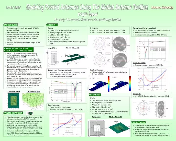
L-shaped slit Probe feed Shorting Strip Ground Plane Patch Dielectric Patch Microstrip Modeling Printed Antennas Using The Matlab Antenna Toolbox Clemson University SURE 2006 Wajih Iqbal Faculty Research Advisor: Dr. Anthony Martin BACKGROUND ANTENNA I Return Loss Convergence Study • The return loss was plotted for 50 frequency points • A finer mesh was used each time • Computation times ranged from 40 to 180 mins Design • This is a Planar Inverted-F Antenna (PIFA) • Rectangular patch = 36x16 mm2 • L-Shaped slit width = 1 mm • Shorting strip width = 2.5 mm • Ground plane = 18x80 mm2 • Air substrate present between the patch and ground plane Directivity • At 1.9 GHz the max. directivity is approx. 3.5 dB • At 2.3 GHz the max. directivity is approx. 1.2 dB • Graduate students usually use Ansoft HFSS for antenna modeling • Too complicated and expensive for undergrads • A much easier and user-friendly code has been developed by Makarov (Worcester Polytechnic Institute) called the Matlab Antenna Toolbox (MAT) • The code is reasonably precise for simple printed antennas 1.9 GHz Patch Matlab 3D model Aerial View NUMERICAL SOLUTION VIA INTEGRAL EQUATION AND MOM • The MAT codes obtain a solution by solving surface and volume integral equations via the method of moments (MOM) • In MOM, the current on metals and the fields in dielectrics are approximated by special functions (basis functions) defined over sub-domains or sub-regions on/near the antenna • The currents are approximated over triangular sub-domains defined on metal surfaces while the fields are approximated in tetrahedrons defined in the dielectric around the antenna • These triangles & tetrahedrons define a mesh or grid which represents an electromagnetic/numerical model of the antenna • Meshes with many triangles and tetrahedrons result in large memory and computer-time requirements • One must be careful to ensure a representative and sufficiently refined mesh to get useful numerical solutions that can be used to accurately predict characteristics of real-world antennas 2.3 GHz Patch Input Impedance • Resonant frequency is approx. 1.67 GHz Surface Currents • The magnitude of surface currents are calculated at 1.9 and 2.3 GHz Return Loss Convergence Study • The return loss was plotted for 70 frequency points with a frequency range of 1.4-2.6 GHz • A finer mesh was used each time 2.3 GHz 1.9 GHz Triangularmesh Tetrahedron grid Directivity • At 1.67 GHz the max. directivity is approx. 4.5 dB ANTENNA II Design • This is a microstrip-fed wide-slot antenna • Square patch = 110x110 mm2 • Wide slot = 53.7x53.7 mm2 • Microstrip = 31.5x1.5 mm2 • Ground plane = 110x110 mm2 • 0.8 mm thin FR4 substrate (εr=4.4) present between the patch and ground plane Input Impedance • Found with 3292 triangle mesh • Resonant frequencies are approx. 1.9 and 2.3 GHz PRINTED ANTENNAS Aerial View Matlab 3D model • Printed antennas are low-profile planar structures that utilize printed circuit board (PCB) technology • They are compact, low cost, easy to manufacture and suitable for integration with electronic systems • Multi-band operation can also be achieved by integrating several coupled printed antenna elements of different lengths and geometries on the same PCB • Dimension can be smaller with higher dielectric • Uses: GPS, Radar, Satellite communication, Military, cell phones, and wireless laptops FUTURE WORK • Simulate more multiband antennas accordingly with future wireless communication needs • Incorporate the genetic algorithm with the code for antenna optimization • After convergence studies construct and test a multiband antenna in the spherical near field chamber