Download
1 / 38
390 likes | 616 Views
CS263 Lecture 5: Logical Database Design Can express the structure of a relation by a Tuple, a shorthand notation Name of the relation is followed (in parentheses) by the names of the attributes of that relation, e.g.: EMPLOYEE1(Emp_ID,Name,Dept,Salary)

E N D
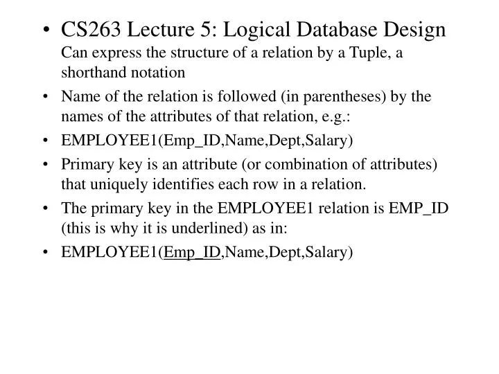
CS263 Lecture 5: Logical Database Design Can express the structure of a relation by a Tuple, a shorthand notation • Name of the relation is followed (in parentheses) by the names of the attributes of that relation, e.g.: • EMPLOYEE1(Emp_ID,Name,Dept,Salary) • Primary key is an attribute (or combination of attributes) that uniquely identifies each row in a relation. • The primary key in the EMPLOYEE1 relation is EMP_ID (this is why it is underlined) as in: • EMPLOYEE1(Emp_ID,Name,Dept,Salary)
Composite key - primary consisting of more than one attribute - e.g., the for relation DEPENDENT would be combination of Emp-ID and Dependent_Name Foreign key - used to represent relationship between two tables - is an attribute (possibly composite) that serves as the primary key of another relation in same database, e.g: EMPLOYEE1(Emp_ID,Name,Dept_Name,Salary) DEPARTMENT(Dept_Name,Location,Fax) Dept_Name is foreign key in EMPLOYEE1 - allows user to associate any employee with department they are assigned to. Some authors show foreign key using dashed underline.
Conceptual schema - description of overall logical structure of database. Two methods for expressing it: A) Short text statements - each relation is named and names of its attributes follow in parentheses • CUSTOMER(Customer_ID, Customer_Name, Address, City, State, Zip) • ORDER(Order_ID, Order_Date, Customer_ID) • ORDER_LINE(Order_ID, Product_ID, Quantity) • PRODUCT(Product_ID, Product_Description, Product_Finish, Standard_Price, On_Hand) B) Graphical representation - each relation represented by rectangle containing attributes for the relation (better for expressing referential integrity constraints (see later))
Note that the primary key for ORDER_LINE is a composite key consisting of the attributes Order_ID and Product_ID • Also, Customer_ID is a foreign key in the ORDER relation, allowing the user to associate an order with a customer • ORDER_LINE has two foreign keys, Order_ID and Product_ID, allowing the user to associate each line on an order with the relevant order and product • A graphical representation of this schema is shown in the following Fig.
Primary Key Foreign Key (implements 1:N relationship between customer and order) Combined, these are a composite primary key (uniquely identifies the order line)…individually they are foreign keys (implement M:N relationship between order and product) Schema for four relations (Pine Valley Furniture)
Integrity constraints - maintain accuracy and integrity of the data • Domain constraints - domain is set of allowable values for attribute. • Domain definition - 4 components: domain name, meaning, data type, size (or length), allowable values/allowable range (if applicable) • Entity Integrity - ensures every relation has primary key, and all data values for primary key are valid. No primary key may be null. • Sometimes attribute cannot be assigned value, e.g. when there is no applicable data value or the value is not known when other values are assigned – here can assign a null value • But still primary key values cannot be null
Referential Integrity Constraint - rule that maintains consistency among rows of two relations – states that any foreign key value (on the relation of the many side) MUST match a primary key value in the relation of the one side. (Or the foreign key can be null) In Fig., an arrow has been drawn from each foreign key to its associated primary key. Referential integrity constraint must be defined for each of these arrows in the schema
Referential integrity constraints (Pine Valley Furniture) Referential integrity constraints are drawn via arrows from dependent to parent table
Referential Integrity - How do you know if a foreign key is allowed to be null? • E.g. as each ORDER must have a CUSTOMER, foreign key of Customer_ID cannot be null on the ORDER relation • Whether a foreign key can be null must be specified as property of the foreign key attribute when the database is designed - can be complex to model, e.g. what happens to order data if we choose to delete customer with orders? May want to see sales even though do not care about customer anymore.
3 possibilities for maintaining referential integrity: • Restrict – don’t allow delete of “parent” side if related rows exist in “dependent” side, i.e. prohibit deletion of the customer until all associated orders are first deleted • Cascade – automatically delete “dependent” side rows that correspond with the “parent” side row to be deleted, i.e. delete the associated orders, in which case we lose not only the customer but also the sales history • Set-to-Null – set foreign key in the dependent side to null if deleting from the parent side - an exception that says although an order must have a customer_ID value when the order is created, Customer_ID can become null later if the associated customer is deleted [not allowed for weak entities]
CREATE TABLE CUSTOMER (CUSTOMER_ID VARCHAR(5) NOT NULL CUSTOMER_NAME VARCHAR(25) NOT NULL Etc. PRIMARY KEY (CUSTOMER_ID); CREATE TABLE ORDER (ORDER_ID CHAR(5) NOT NULL ORDER_DATE DATE NOT NOT NULL CUSTOMER_ID VARCHAR(5) NOT NULL PRIMARY KEY (ORDER_ID) FOREIGN KEY (CUSTOMER_ID) REFERENCES CUSTOMER(CUSTOMER_ID);
Referential integrity constraints easily defined using graphical schema • Arrow originates from each foreign key and points related primary key in the associated relation • FOREIGN KEY REFERENCES statement corresponds to one of these arrows • Foreign key CUSTOMER_ID references the primary key of CUSTOMER, which is also CUSTOMER_ID • Although here the foreign and primary keys have the same name, this need not be the case – but the foreign and primary keys must be from the same domain
The ORDER_LINE table illustrates how to specify a primary key when that key is a composite attribute of two foreign keys: CREATE TABLE ORDER_LINE (ORDER_ID CHAR(5) NOT NULL PRODUCT_ID CHAR(5) NOT NULL QUANTITY INT NOT NULL PRIMARY KEY(ORDER_ID, PRODUCT_ID) FOREIGN KEY (ORDER_ID) REFERENCES ORDER(ORDER_ID) FOREIGN KEY (PRODUCT_ID) REFERENCES PRODUCT(PRODUCT_ID);
Step 1: map regular entities • Each regular entity type in an ER diagram is transformed into a relation • The name given to the relation is generally the same as the entity type • Each simple attribute of the type becomes an attribute of the relation • The identifier of the entity type becomes the primary key of the corresponding relation • The following 2 Figs. show an example of this
Mapping a regular entity (a) CUSTOMER entity type with simple attributes (b) CUSTOMER relation
Composite attributes • When a regular entity type has composite attributes, only the simple component attributes of the composite attribute are included in the new relation • The following Fig. Shows a variation on the previous one, where Customer_Address is represented as a composite attribute with components Street, City, State and Zip
Mapping a composite attribute (a) CUSTOMER entity type with composite attribute (b) CUSTOMER relation with address detail
Multi-valued attributes • Here two new relations (rather than one) are created • First relation contains all of the attributes of the entity type except the multivalued attribute • Second relation contains two attributes that form the primary key of the second relation • The first of these is the primary key for the first relation, which becomes a foreign key in the second relation • The second is the multivalued attribute
Multi-Valued Attributes: In Fig. EMPLOYEE has ‘Skill’ as multi-valued attribute • EMPLOYEE has the primary key Employee_ID • EMPLOYEE_SKILL has two attributes Employee_ID and Skill, which form primary key • Relationship between foreign and primary keys is indicated by the arrow
Multivalued attribute becomes a separate relation with foreign key (b) Mapping a multivalued attribute (a) 1 – to – many relationship between original entity and new relation
Step 2 - Map Weak Entities - must already have created a relation corresponding to the identifying type • For each WE create new relation including all simple attributes (or simple components of composite attributes) • Then include PK of the identifying relation as a foreign key in this new relation • PK of new relation is the combination of this PK of the identifying and the partial identifier of the WE • In Fig. Dependent_Name (partial identifier) is composite attribute, components First_Name, Middle_Initial and Last_Name – assume for given employee these items will uniquely identify a dependent. • PK of DEPENDENT has four attributes: Employee_ID, First_Name, Middle_Initial,Last_Name
Example of mapping a weak entity (a) Weak entity DEPENDENT
Composite primary key Relations resulting from weak entity NOTE: the domain constraint for the foreign key should NOT allow null value if DEPENDENT is a weak entity Foreign key
Step 3: map binary relationships First map binary (1..m) relationships (one to many) • First create a relation for each of the two entity types participating in the relationship • Next include the primary key attribute(s) of the entity on the one-side as a foreign key in the relation that is on the many-side • ‘Submits’ relationship in the following Fig. shows the primary key Customer_ID of CUSTOMER (the one-side) included as a foreign key in ORDER (the many-side) (signified by the arrow)
Example of mapping a 1:M relationship Relationship between customers and orders Note the mandatory one
Figure 5-12(b) Mapping the relationship Again, no null value in the foreign key…this is because of the mandatory minimum cardinality Foreign key
Map binary many-to-many (M:N) relationships (if they exist) • Create a new relation C, then include as foreign keys in C the primary keys for A and B, then these attributes become the primary key of C • In the following Fig., first a relation is created for VENDOR and RAW_MATERIALS, then a relation QUOTE is created for the ‘Supplies’ relationship – with primary key formed from a combination of Vendor_ID and Material_ID (primary keys of VENDOR and RAW_MATERIALS). • These are foreign keys that point to the respective primary keys
The Supplies relationship will need to become a separate relation Example of mapping an M:N relationship ER diagram (M:N)
Composite primary key Foreign key Foreign key Three resulting relations New intersection relation
Map binary one-to-one relationships - can be viewed as special case of one-to-many relationships. • Firstly, two relations are created, one for each of participating entity types • Secondly, PK of one of the relations included as a FK key in the other relation • In a 1:1 relationship, the association in one direction is nearly always optional one, whilst the association in the other direction is mandatory one • Should include in relation on the optional side of relationship FK of the entity that has mandatory participation in the 1:1 relationship (avoids need to store null values in the foreign key attribute)
Attributes associated with the relationship itself included in the same relation as the foreign key • Fig. Shows binary 1:1 relationship between NURSE and CARE_CENTER - each care centre must have a nurse in charge of that centre – the association from care centre to nurse is mandatory one, while association from nurse to care centre is an optional one (since any nurse may or may not be in charge of a care centre) • Attribute Date_Assigned attached to In_Charge relationship • CARE_CENTER is the optional participant - FK (Nurse_In_Charge) placed in this relation • Attribute Date_Assigned also located in CARE_CENTER - not be allowed to be null
Mapping a binary 1:1 relationship Binary 1:1 relationship
Step 4: map associative entities - when user can best visualise relationship as an associative entity (rather than an M:N relationship) follow similar steps to mapping an M:N relationship • Three relations created, one for each of the two participating entities and third for the associative entity • Relation formed is called the associative relation • Next step depends on whether on the ER diagram an identifier was assigned to the associative entity • Identifier not assigned - default PK for the associative relation consists of the two PKs from other two relations • These are then FKs that reference the other two relations
Identifier assigned – sometimes surrogate identifier or key is assigned to the associative entity on ER diagram. 2 possible reasons: • A) Associative identity type has a natural identifier that is familiar to end users • B) Default identifier (consisting of identifiers for each of participating entities) may not uniquely identify instances of associative identity • As before new associative relation created to represent the associative entity • However, PK for this relation is identifier assigned on the ER diagram (rather than default key) • PKs for the two participating entities then included as FKs in the associative relation
Fig. Shows associative entity SHIPMENT linking CUSTOMER and VENDOR entity types • Shipment_No chosen as the identifier for two reasons: • 1. Shipment_No is natural identifier for this entity - familiar to end users • 2. Default identifier consisting of combination of Customer_ID and Vendor_ID does not uniquely identify the instances of shipment - given vendor will make many shipments to a given customer • New associative relation is named SHIPMENT – PK Shipment_No. • Customer_ID and Vendor_ID are included as foreign keys in this relation
Mapping an associative entity Associative entity