Download
1 / 40
400 likes | 514 Views
B. V. alues represented. Sign and. b. b. b. b. magnitude. 1'. s complement. 2'. s complement. 3. 2. 1. 0. +. 7. +. 7. +. 7. 0. 1. 1. 1. +. 6. +. 6. +. 6. 0. 1. 1. 0. +. 5. +. 5. +. 5. 0. 1. 0. 1. +. 4. +. 4. +. 4. 0. 1. 0. 0. +. 3. +. 3.

E N D
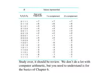
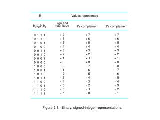
B V alues represented Sign and b b b b magnitude 1' s complement 2' s complement 3 2 1 0 + 7 + 7 + 7 0 1 1 1 + 6 + 6 + 6 0 1 1 0 + 5 + 5 + 5 0 1 0 1 + 4 + 4 + 4 0 1 0 0 + 3 + 3 + 3 0 0 1 1 + 2 + 2 + 2 0 0 1 0 + 1 + 1 + 1 0 0 0 1 + 0 + 0 + 0 0 0 0 0 - 0 - 7 - 8 1 0 0 0 - 1 - 6 - 7 1 0 0 1 - 2 - 5 - 6 1 0 1 0 - 3 - 4 - 5 1 0 1 1 - 4 - 3 - 4 1 1 0 0 - 5 - 2 - 3 1 1 0 1 - 6 - 1 - 2 1 1 1 0 - 7 - 0 - 1 1 1 1 1 Figure 2.1. Binary, signed-integer representations.
0 1 0 1 + 0 + 0 + 1 + 1 0 1 1 1 0 Carry-out Figure 2.2. Addition of 1-bit numbers.
Please see “portrait orientation” PowerPoint file for Chapter 2 Figure 2.3. Modular number systems and the 2's-complement system.
Please see “portrait orientation” PowerPoint file for Chapter 2 Figure 2.4. 2's-complement Add and Subtract operations.
Please see “portrait orientation” PowerPoint file for Chapter 3 Figure 2.5. Memory words.
32 bits • • • b b b b 31 30 1 0 for positive numbers Sign bit: b = 0 31 for negative numbers b = 1 31 (a) A signed integer 8 bits 8 bits 8 bits 8 bits ASCII ASCII ASCII ASCII character character character character (b) Four characters Figure 2.6.Examples of encoded information in a 32-bit word.
W ord address Byte address Byte address 0 0 1 2 3 0 3 2 1 0 4 4 5 6 7 4 7 6 5 4 • • • • • • k k k k k k k k k k 2 - 4 2 - 4 2 - 3 2 - 2 2 - 1 2 - 4 2 - 1 2 - 2 2 - 3 2 - 4 (a) Big-endian assignment (b) Little-endian assignment Figure 2.7. Byte and word addressing.
Please see “portrait orientation” PowerPoint file for Chapter 2 Figure 2.8.. A program for C ¬ [A] + [B].
Please see “portrait orientation” PowerPoint file for Chapter 2 Figure 2.9. A straight-line program for addingn numbers.
Please see “portrait orientation” PowerPoint file for Chapter 2 Figure 2.10. Using a loop to addn numbers.
Add (R1),R0 Add (A),R0 Main memory B Operand A B Register Operand R1 B B (a) Through a general-purpose register (b) Through a memory location Figure 2.11. Indirect addressing.
Address Contents Move N,R1 Initialization Move #NUM1,R2 Clear R0 LOOP Add (R2),R0 Add #4,R2 Decrement R1 LOOP Branch>0 Move R0,SUM Figure 2.12. Use of indirect addressing in the program of Figure 2.10.
Please see “portrait orientation” PowerPoint file for Chapter 2 Figure 2.13. Indexed addressing.
Please see “portrait orientation” PowerPoint file for Chapter 2 Figure 2.14. A list of students' marks.
Move #LIST,R0 Clear R1 Clear R2 Clear R3 Move N,R4 Add 4(R0),R1 LOOP Add 8(R0),R2 A d d 12(R0),R3 Add #16,R0 Decrement R4 Branch>0 LOOP Move R1,SUM1 R2,SUM2 Move Move R3,SUM3 Figure 2.15. Indexed addressing used in accessing test scores in the list in Figure 2.14.
Move N,R1 Initialization Move #NUM1,R2 Clear R0 LOOP Add (R2)+,R0 Decrement R1 Branch>0 LOOP Move R0,SUM Figure 2.16. The Autoincrement addressing mode used in the program of Figure 2.12.
Please see “portrait orientation” PowerPoint file for Chapter 2 Figure 2.17. Memory arrangement for the program in Figure 2.12.
Memory Addressing address or data lab el Op eration information Assem bler directiv es SUM EQU 200 ORIGIN 204 N D A T A W ORD 100 NUM1 RESER VE 400 ORIGIN 100 Statemen ts that ST AR T MO VE N,R1 generate MO VE #NUM1,R2 mac hine CLR R0 instructions LOOP ADD (R2),R0 ADD #4,R2 DEC R1 BGTZ LOOP MO VE R0,SUM Assem bler directiv es RETURN END ST AR T Figure 2.18. Assembly language representation for the program in Figure 2.17.
Mo v e #LOC,R0 Initialize p oin ter register R0 to p oin t to the address of the first lo cation in memory where the c haracters are to b e stored. READ T estBit #3,INST A TUS W ait for a c haracter to b e en tered Branc h=0 READ in the k eyb oard buffer D A T AIN. Mo v eByte D A T AIN,(R0) T ransfer the c haracter from D A T AIN in to the memory (this clears SIN to 0). ECHO T estBit #3,OUTST A TUS W ait for the displa y to b ecome ready . Branc h=0 ECHO Mo v eByte (R0),D A T A OUT Mo v e the c haracter just read to the displa y buffer register (this clears SOUT to 0). Compare #CR,(R0)+ Chec k if the c haracter just read is CR (carriage return). If it is not CR, then Branc h READ branc h bac k and read another c haracter. 0 Also, incremen t the p oin ter to store the next c haracter. Figure 2.20. A program that reads a line of characters and displays it.
Please see “portrait orientation” PowerPoint file for Chapter 2 Figure 2.21. A stack of words in the memory.
Please see “portrait orientation” PowerPoint file for Chapter 2 Figure 2.22. Effect of stack operations on the stack in Figure 2.21.
SAFEPOP Compare #2000,SP Chec k to see if the stac k p oin ter con tains Branc h > 0 EMPTYERR OR an address v alue greater than 2000. If it do es, the stac k is empt y . Branc h to the routine EMPTYERR OR for appropriate action. Mo v e (SP)+,ITEM Otherwise, p op the top of the stac k in to memory lo cation ITEM. (a) Routine for a safe pop operation SAFEPUSH Compare #1500,SP Chec k to see if the stac k p oin ter Branc h 0 FULLERR OR con tains an address v alue equal to or less than 1500. If it do es, the stac k is full. Branc h to the routine FULLERR OR for appropriate action. – Mo v e NEWITEM, (SP) Otherwise, push the elemen t in memory lo cation NEWITEM on to the stac k. (b) Routine for a safe push operation Figure 2.23. Checking for empty and full errors in pop and push operations.
Please see “portrait orientation” PowerPoint file for Chapter 2 Figure 2.24. Subroutine linkage using a link register.
Calling program Mo v e N,R1 R1 serv es as a coun ter. Mo v e #NUM1,R2 R2 p oints to the list. Call LIST ADD Call subroutine. Mo v e R0,SUM Sa v e result. . . . Subroutine LIST ADD Clear R0 Initialize sum to 0. LOOP Add (R2)+,R0 Add en try from list. Decremen t R1 Branc h LOOP > 0 Return Return to calling program. Figure 2.25. Program of Figure 2.16 written as a subroutine; parameters passed through registers.
Please see “portrait orientation” PowerPoint file for Chapter 2 Figure 2.26. Program of Figure 2.16 written as a subroutine; parameters passed on the stack.
Please see “portrait orientation” PowerPoint file for Chapter 2 Figure 2.27. A subroutine stack frame example.
Please see “portrait orientation” PowerPoint file for Chapter 2 Figure 2.28. Nested subroutines.
Please see “portrait orientation” PowerPoint file for Chapter 2 Figure 2.29. Stack frames for Figure 2.28.
Please see “portrait orientation” PowerPoint file for Chapter 2 Figure 2.30. Logical and arithmetic shift instructions.
Mo v e #LOC,R0 R0 points to data. Mo v eByte (R0)+,R1 Load first b yte in to R1. LShiftL #4,R1 Shift left b y 4 bit p ositions. Mo v eByte (R0),R2 Load second b yte in to R2. And #$F,R2 Eliminate high-order bits. Or R1,R2 Concatenate the BCD digits. Mo v eByte R2,PACKED Store the result. Figure 2.31. A routine that packs two BCD digits.
Please see “portrait orientation” PowerPoint file for Chapter 2 Figure 2.32. Rotate instructions.
Mo v e #A VEC,R1 R1 p oin ts to v ector A. Mo v e #BVEC,R2 R2 p oin ts to v ector B. Mo v e N,R3 R3 serv es as a coun ter. Clear R0 R0 accum ulates the dot pro duct. LOOP Mo v e (R1)+,R4 Compute the pro duct of Multiply (R2)+,R4 next comp onen ts. Add R4,R0 Add to previous sum. Decremen t R3 Decremen t the coun ter. Branc h LOOP Loop again if not done. > 0 Mo v e R0,DOTPR OD Store dot pro duct in memory . Figure 2.33. A program for computing the dot product of two vectors.
Please see “portrait orientation” PowerPoint file for Chapter 2 Figure 2.34. A byte-sorting program using a straight-selection sort.
Link address Record 1 Record 2 Record k 0 Head T ail (a) Linking structure Record 2 Record 1 Ne w record (b) Inserting a new record between Record 1 and Record 2 Figure 2.35. Linked-list data structure.
Please see “portrait orientation” PowerPoint file for Chapter 2 Figure 2.36. A list of student test scores organized as a linked list in memory.
Please see “portrait orientation” PowerPoint file for Chapter 2 Figure 2.37. A subroutine for inserting a new record into a linked list.
DELETION Compare (RHEAD), RIDNUM Branch>0 SEARCH Mo v e 4(RHEAD), RHEAD not the head record Return Mo v e RHEAD, RCURRENT SEARCH LOOP Mo v e 4(RCURRENT), RNEXT Compare (RNEXT), RIDNUM Branch=0 DELETE Mo v e RNEXT , RCURRENT Branch LOOP DELETE Mo v e 4(RNEXT), R TEMP Mo v e R TEMP , 4(RCURRENT) Return Figure 2.38. A subroutine for deleting a record from a linked list.
Please see “portrait orientation” PowerPoint file for Chapter 2 Figure 2.39. Encoding instructions into 32-bit words.
Please see “portrait orientation” PowerPoint file for Chapter 2 Table 2.1. Generic addressing modes.