Download
1 / 30
300 likes | 424 Views
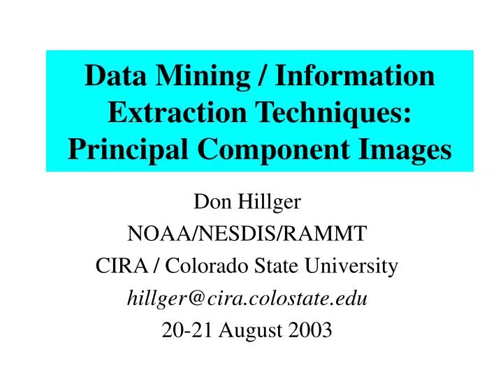
Data Mining / Information Extraction Techniques: Principal Component Images. Don Hillger NOAA/NESDIS/RAMMT CIRA / Colorado State University hillger@cira.colostate.edu 20-21 August 2003. Principal Component Image (PCI) transformation of multi-spectral imagery. Terminology/Definitions:

E N D
Data Mining / Information Extraction Techniques:Principal Component Images Don Hillger NOAA/NESDIS/RAMMT CIRA / Colorado State University hillger@cira.colostate.edu 20-21 August 2003
Principal Component Image (PCI) transformation of multi-spectral imagery Terminology/Definitions: • PCI = Principal Component Image – a new image combination • Eigenvectors = transformation vectors to create PCIs from multi-spectral imagery • Eigenvalues = explained variances (weights) of the principal component images
Why transform imagery? • To simplify multi-spectral imagery by reducing redundancy to obtain the independent information • A new set of images that are optimal combinations of the original spectral-band images for extracting the variance in the available imagery • Important image combinations for detection of atmospheric and surface features in multi-spectral data
General Case band(N) PCI(N) • The number of component images resulting from a PCI transformation is equal to the number of spectral-band images input. • The sum of the explained variances of the component images is equal to the sum of the explained variances of the original images (the same information content as the original imagery expressed in a new form)
General Case PCI = E @ B where: • PCI = transformed set of N images, at M horizontal locations (pixels) • E = N by N transformation matrix. The rows of E are the eigenvectors of the symmetric matrix with elements determined by the covariance of each band with every other band (summed over M pixels) • B = set of imagery from N bands, viewing a scene at M horizontal locations (pixels)
Two-dimensional Case pci1 = e1 @ band1 + e2 @ band2 pci2 = f1 @ band1 + f2 @ band2 where: pci1 and pci2 = Principal Component Images (PCIs) band1 and band2 = band images e and f = linear transformation vectors (eigenvectors, or rows in the eigenvector matrix E). In the two-dimensional case: pci1 usually contains the information that is common to the band1 and band2 images pci2 contains the information that is different between the band1 and band2 images.
2-dimensional case – Montserrat / Soufriere Hills volcano 2 bands 2 PCIs
2-dimensional case – Montserrat / Soufriere Hills volcano Comparison to ash-cloud analysis
5-band transform(GOES Imager) 5 bands 5 PCIs
Signal-to-Noise(GOES Imager) 5 bands 5 PCIs
19-band transform(GOES Sounder) 19 bands 19 PCIs
Signal-to-Noise(GOES Sounder) 19 bands 19 PCIs
Principal Component Images of fire hot spots and smoke clouds clouds smoke smoke rings of fire Arizona fires – 21 June 2002 1806 UTC (MODIS)
Principal Component Images of fire hot spots and smoke smoke rings of fire smoke Arizona fires – 23 June 2002 1754 UTC (MODIS)
In conclusion:Why transform imagery? • To simplify multi-spectral imagery by reducing redundancy to obtain the independent information • A new set of images that are optimal combinations of the original spectral-band images for extracting the variance in the available imagery • Important image combinations for detection of atmospheric and surface features in multi-spectral data