Download

1 / 43
430 likes | 583 Views
Development of an Implantable Radio Identification Tag For Steller Sea Lion Pups. Simon Fraser University. Hamid Meghdadi Summer 2006. Headlines. Simon Fraser University Introduction Tool and Utilities Tests and Measurements Conclusion. Simon Fraser University.

E N D
Development of an Implantable Radio Identification Tag For Steller Sea Lion Pups Simon Fraser University Hamid Meghdadi Summer 2006
Headlines • Simon Fraser University • Introduction • Tool and Utilities • Tests and Measurements • Conclusion
Simon Fraser University • Location: Vancouver, BC, Canada • Established: September 1965 • Students: 25000 • Annual expenses: $300 million • School of engineering science: • Since 1983 • M.Eng, M.Sc, Ph.D
Steller Sea Lions: Endangered species Unknown mortal rate Unknown immigration pattern Existing Tags: Glued: fall off Large Surgically invasive Limited life span Introduction Design an Implantable Radio Identification Tag
Reporting base station Implanted tag will be on for 1 ms every hr Introduction Design Targets: • 2-3 years life span (power management) • Identity • Biocompatible • Report rate (1/hr) • 3 x 6.5 x 0.3 cm • Radio tag • $100
Receiver: • Receives the information • Detects the tag • Sends data to computer • Computer: • Receives the information • Analyses data • Saves reports for biologist • Tag: • Wakes up every hour • Sends its identification code Introduction Tag Base Station
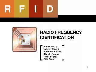
RF Identification Tags IA4420 Transceiver MSP430 Microcontroller Matching Network Loop Antenna JTAG Interface Substrate Electronic components Loop antenna
Microcontroller Antenna and matching network Transceiver JTAG Interface RF Identification Tags
Final Robust Construction Link budget (?) Placement(?) => Research Prototype (Test) Receive data Save log Evaluate tag’s efficiency Use available components Base Station
MSP430 μ-Controller IA 4420 Transceiver MSC-DKLB1 Board StratixII FPGA Board LabVIEW TI MSP430 Family: Ultra-low-power 16 bit RISC CPU Integrated peripherals USART ADC ... Flexible clock system Internal External Integrated E²PROM, RAM and Flash memories. Tools and utilities
MSP430 μ-Controller IA 4420 Transceiver MSC-DKLB1 Board StratixII FPGA Board LabVIEW Integration’s IA4420: Multi-channel FSK transceiver Unlicensed use in 315, 433, 868, 915 MHz Low-power SPI Interface VDI, ARSSI Wake-up timer Interrupts: POR Wake-up timeout TX Empty or RX Full … Tools and utilities
MSP430 μ-Controller IA 4420 Transceiver MSC-DKLB1 Board StratixII FPGA Board LabVIEW MSC-DKLB1 Evaluation Board Interface between PC and IA chip Serial RS232 Interface to PC PC End utility: Any terminal simulator program (Hyper Terminal) WDS (User Friendly Interface) Capable of: Sending SPI commands to the chip Driving chip inputs high or low Monitoring chip outputs Reading RX FIFO and Status Registers Tools and utilities
MSP430 μ-Controller IA 4420 Transceiver MSC-DKLB1 Board StratixII FPGA Board LabVIEW StratixII DSP Development Board Development platform for high-performance DSP design Components: A/D and D/A VGA Output Audio CODEC RS-232 Interface Dual 7 Segment display Switches and LEDs … Tools and utilities
MSP430 μ-Controller IA 4420 Transceiver MSC-DKLB1 Board StratixII FPGA Board LabVIEW NI LabVIEW Programming tool G-Code based Built-in functions Applications: Instrumentation Industrial control systems Tools and utilities
Tests and Measurements • Communicating with IA4420 • DC Power Requirements • Power Consumption Test • Transmission Efficiency Test 1 • Transmission Efficiency Test 2 • Bit Error Rate Test
Communicating with IA4420 (Transmitter Mode) Two Transmission Modes: • FSK Input Active • Data at FSK input is transmitted • Bit rate controlled manually • TX register not used • TX Register Buffered • FSK input must be high • Data delivered to chip via SPI link • Bit rate controlled internally nSEL SCK SDI IA4420 FSK nIRQ
Communicating with IA4420 (Transmitter Mode) nSEL SCK SDI IA4420 FSK • Configuration Setting Command • Power Management Command • Data Rate Command • Status Read Command nIRQ
Communicating with IA4420 (Transmitter Mode) nSEL SCK SDI IA4420 FSK • Configuration Setting Command • Frequency Band • Oscillator load capacitor • Power Management Command • Data Rate Command • Status Read Command nIRQ
Communicating with IA4420 (Transmitter Mode) nSEL SCK SDI IA4420 FSK • Configuration Setting Command • Power Management Command • Receive/Transmit • Wake-up timer • PA, XTAL, … • Data Rate Command • Status Read Command nIRQ
Communicating with IA4420 (Transmitter Mode) nSEL SCK SDI IA4420 FSK • Configuration Setting Command • Power Management Command • Data Rate Command • Status Read Command nIRQ
Communicating with IA4420 (Transmitter Mode) nSEL Interrupt Events: • TX register ready • POR • TX register overflow • Wake-up timer timeout • Low Battery Detect SCK SDI IA4420 FSK nIRQ
Communicating with IA4420 (Receiver Mode) nSEL Two Reception Modes: • FIFO not used • FSK: Received data • DCLK: Data clock • RX FIFO not used • FIFO Mode • Data is stored in a 16 bit FIFO • FIFO can be read by SPI link SCK SDI IA4420 FSK DCLK nIRQ ARSSI VDI
Communicating with IA4420 (Receiver Mode) nSEL Interrupt Events: • FIFO Full • POR • FIFO overflow • Wake-up timer timeout • Low Battery Detect SCK SDI IA4420 FSK DCLK nIRQ ARSSI VDI
Communicating with IA4420 (Receiver Mode) nSEL Data Detection: • VDI • Valid Data Indicator • Digital signal • Slow • ARSSI • Analog Received Signal Strength Indicator • Fast SCK SDI IA4420 FSK DCLK nIRQ ARSSI VDI
DC Power Requirements Objective: Determine the best supply voltage for the tag IDC Tag POut Spectrum Analyzer Power Supply VDD
DC Power Requirements VDD=2.2 V
Power Consumption Test Objective: Power consumption of tag in its different states 3 Bytes 3 Bytes 3 Bytes 2 Sec 2 Sec • The Tag will wake up every 2 seconds • On each wake-up event, tag will transmit 24 bits • The current pass through the tag is measured continuously
Power Consumption Test Main Program Interrupt Service routine (Wake-up event activated)
Power Consumption Test 1) Wake-up timer expires 2) Micro reads interrupt → Interrupt released 3) Micro enables transmission 5) PA on, transmission starts → Max power (I=22 mA) 6) One byte is transmitted, TX is empty 7) Micro sets next byte for transmission, TX no longer empty 8) Transmission finished 9) Tag goes back to sleep mode
Valid Packet: • VDI = High • Preamble & Sync Correct Transmission Efficiency Test 1 Objective: Evaluate tag’s efficiency and reliability 3 Bytes 3 Bytes 3 Bytes 2 Sec 2 Sec • The Tag will wake up every 2 seconds • On each wake-up event, tag will transmit 24 bits • Base station waits for a valid packet and creates a report
USB JTAG USB JTAG RS-232 Tag RS-232 GND, VDI, CLK, DATA Base Station Transmission Efficiency Test 1 Programming phase: • Programming tag • Programming FPGA • Configuring IA evaluation board Running phase: • Tag transmits a packet every 2 seconds • IA board receives data and provides DATA, CLK, VDI • FPGA reads these lines, detects packet, Sends to PC • LabVIEW reads from RS-232, saves report
Transmission Efficiency Test 1 Search Communicate • Searches for a packet • Timer counts • Max → LED • Data byte → 7 Segment • Timer reset to zero • Send character to PC
MSB Data (23 downto 0) LSB 23 … 19 … 7 6 … 0 DATA_IN =“01010”“11011011” ? Valid data Transmission Efficiency Test 1
Transmission Efficiency Test 1 LabVIEW Program
3 Bytes 3 Bytes 3 Bytes Transmission Efficiency Test 1 • Results not very good • Range ≈ 1m • Efficiency < 90% • VDI too slow • A better VDI is required FPGA will not detect this packet VDI
Transmission Efficiency Test 2 • Final test postponed • CVDI more reliable • Results much better • Range ≈ 1 km • Efficiency > 95% • Improvements possible
Bit Error Rate Test • Objective: Estimate the BER of the link • Tag will transmit continuously • Base station will: • Receive the data • Compare received data with expected data • Count the number of erred bits • Display the BER estimation on request The tag will transmit this pattern: One Packet
Bit Error Rate Test FPGA state machine:
Bit Error Rate Test Bit error calculation circuit Seven Segment Display Circuit
Transmission Efficiency Test 2 LabVIEW Program
Next steps for project: A more efficient antenna for base station Evaluate efficiency of implanted tags when animal moves in different environments Battery selection Using an array antenna and diversity techniques in base station Characterize the link budget by the range and environment Personal advantages: Autonomy Telecommunications knowledge Antenna matching Fading effect FSK mod/dem Bit rate & deviation vs. quality FPGA and microprocessors knowledge Apply basic electronics theory Conclusion