Download
1 / 35
1.75k likes | 4.26k Views
Introduction to CNC. Presented By Bidve M.A. Introduction. Conventionally machines were operated by skilled technician(operator) who determines the various variables like speed, feed, depth of cut, etc. for machining the required component.

E N D
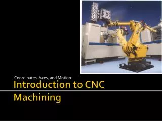
Introduction to CNC Presented By Bidve M.A.
Introduction • Conventionally machines were operated by skilled technician(operator) who determines the various variables like speed, feed, depth of cut, etc. for machining the required component. • On the basis of his experience, he will control the machine tool and produce the various jobs but the operator skill is the critical factor for accuracy and finish of the job.
Limitations of Conventional Machines • It requires skilled operators to perform various operations. • The production time increases if the workpiece is complex and precision manufacturing. • Operator may fatigue and committed mistakes. • Rate of Production is low, not suitable for mass production. • Limited tools can be mounted on tool post. • Longer setup times for machine and tool adjustments.
Numerical Control • NC can be defined as a form of programmable automation in which the process is controlled by numbers, letters and symbols. • It means that it is a technique for controlling the machine tool by using coded instructions in the form of program prepared for the given job. • Manufacturing firms, automation and mass production with flexible system use NC and CNC.
CNC Machines • CNC means Computerized Numerical Control machine. In this meaning the world Numerical control is very important, it replace the operator control of machine to the Numerical Control of machine. • In CNC machines a dedicated computer is used to perform all the basic NC functions the complete part program to produce a component is input and stored in the computer memory. • In simple worlds the machine tool which is operated and controlled by using a dedicated computers is known as CNC.
Definition of CNC • It is defined as the NC system where in a dedicates, stored program computer is used to perform some or all of the basic numerical control programs stored in the read- write memory of the computer. • The software stored in computer performs the functions of data decoding, control, buffering, feed rate control, etc.
Advantages of CNC • Reduced lead time. • Elimination of operator error. • Lower labour cost. • High accuracy. • Elimination of Jig and Fixture. • Flexibility. • Reduced inspection. • Less scarp.
Disadvantages of CNC • Higher investment cost. • Higher maintenance cost. • Costlier CNC personnel. • Planned support facility.
Application of CNC • When operation are very complex. • The number of operation is large. • Batch size is medium. • Batches are often repeated. • Where design changes or individual variations are required. • A large variety of components is produced.
Open Loop Control System • Some CNC machines utilize open loop control system which does not have a feedback device and thus the actual position of the tool slide or work table is not measured and verified.
Principle • This system depends upon the quality of the drive unit. The machine tool is not part of the control system and effect of vibrations and other characteristics of the machine are less critical. • The control system is simple in design less number of components and cheaper compared to closed loop system. • The accuracy is also less hence not suitable for precision applications.
Working • In this control system the NC program in the coded form is given to the tape reader/ program reader which convert it into mechanical commands. • The MCU generates electrical signals to the drive units of spindle/ slides, here it is stepper motor for machine table slide. • There is no provision to measure the actual movement of the slide as no presence of any feedback devices.
The actual movement of the slide may be affected by friction, wear and tear, vibrations, screw errors, etc hence accuracy is less. • The open loop system is restricted to small machine tools because of limited power of stepper motors. • This system offers cost savings for light duty machines where problem of instability are absent and high precision is not required.
Closed Loop Control System • When actual positions of slides, speed of the machine spindle are determined by using feedback devices for detection of error and action is initiated to remove the error then system is called as closed loop system.
Principle • The closed loop means the feedback signal is again brought to the input signal for comparison or error detection hence known as closed loop. • Use of feedback sensors makes the system little complicated and costly. • It gives very high accuracy and suitable for precision application.
Working • This system consists of input device for program, tape reader, MCU, drives for spindle/ slide and mechanical elements. • The main additional component required is feedback sensor/ device to measure actual movement of the machine element. • The feedback device measures the actual movement and gives signal to the computer to compare it with input signal.
If there is a difference/ error occurs it will be send to the MCU for corrective action e.g. slide displacement as per input is 10mm and actual displacement measured by feedback sensor is 9.5mm, then error of 0.5mm occurs. • The MCU will actuate the slide by 10.50mm to get exact 10mm movement of the slide.
Axis Identification • After understanding the constructional details of machining centre, it is important to learn axis identification for machining centre. • During machining of component, it is necessary to move the spindle, slides in a different direction to obtain desired shape of the workpiece.
Linear Axes: The movement are in a straight line by the machine slides and represented as X,Y,Z axes. • Rotary Axes: The movement are rotary about axes for the spindle and designated by A,B and C axes.
Linear Axes • The spindle movement is taken along Z- axis and it is shown by the middle finger of right hand. • Movement along X-axis is perpendicular to the Z-axis and it is shown by thumb of right hand. • Movement along Y-axis is perpendicular to both Z and X-axis and indicated by first finger of right hand.
Rotary Axes • Rotation about an axis parallel to X-axis is A, Y-axis is B, Z-axis is C respectively. • Thumb shows axis direction and finger indicates direction of rotation.
Absolute Co-ordinate System • In this system all co-ordinates of various points are calculated with respect to fixed reference point which is the origin( also called as zero point). • This system is known as fixed zero system. • All positions commands are given as absolute distance from that zero point. • This system is easy and mistake in one point will not affect to the successive point. It will be limited to that particular co-ordinate point. • The G code used for this system is G90.
Incremental Co-ordinate System • In this system co-ordinate of any point is calculated with reference to the previous point. • It means that the reference point is not fixed but it moves from one point to the next point. • It is also called as floating zero system. • This system is complicated as each time reference changes and mistake in one point may effect subsequent points. • It is designated by G code ‘G91’.
Difference between Absolute and Incremental Co-ordinate System
Introduction to G-code • The most common codes used when programming CNC machine tools are G codes, other codes such as F, S, D, T, etc which are used for machine functions such as feed, speed, cutter diameter offset, tool number, etc • G codes are preparatory functions which instruct the machine tool to get prepared for the operation to follow. • G codes are used to give movement of tool/ workpiece in the X, Y, Z axis of machine tool.
Introduction to M-code • The M codes are used for NC machine functions which are not related to dimensional or axial movement. • They are not related to actual machining but executes auxiliary functions like start/ stop spindle, ON/OFF coolant, etc. • It is represented by letter M followed by number.
Part Programming • It is defined as a set of instructions which consists of sequence of processing steps to be performed on CNC machine prepared by the programmer. • It is the planning and documenting the sequence of operations to be carried out on a given job in the form of coded instructions to covert raw material into desired product.
Cutter Radius Compensation • When machining is done by using cutter of different diameters, it will change the centre line path of the movement of cutter axis. • If program is designed separately for a cutter size and if another size of cutter is used during machining then job may be oversize or undersize. • Whenever part is being machined, the programmer must calculate an offset path which is usually half the cutter diameter.