Download
1 / 38
380 likes | 527 Views
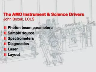
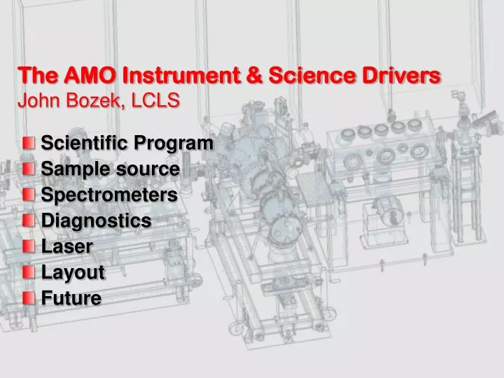
The AMO Instrument & Science Drivers John Bozek, LCLS. Scientific Program Sample source Spectrometers Diagnostics Laser Layout Future. Scientific Goals of the AMO instrumentation. Investigate multiphoton and high-field x-ray processes in atoms, molecules and clusters

E N D
The AMO Instrument & Science DriversJohn Bozek, LCLS • Scientific Program • Sample source • Spectrometers • Diagnostics • Laser • Layout • Future
Scientific Goals of the AMO instrumentation • Investigate multiphoton and high-field x-ray processes in atoms, molecules and clusters • Multi-photon ionization/excitation in atoms/molecules/clusters • Accessible intensity on verge of high-field regime • Study time-resolved phenomena in atoms, molecules and clusters using ultrafast x-rays • Inner-shell side band experiments • Photoionization of aligned molecules • Temporal evolution of state-prepared systems
Proposal Workshop • Held June 2 &3 • Over 60 attendees • Presented team’s scientific program and technical details of instrument • Research interests included: • Aligned molecules – Ryan Coffee, PULSE • LCLS as a laser pump – Nina Rohringer, LLNL • Highly charged ions – Peter Beierdorfer, LLNL • Fundamental damage at high intensity – Linda Young, ANL • Imaging/x-ray emission – Daniel Rolles, CFEL • Single shot timing measurements – Hamed Merdji, CEA • Magneto-Optical trapped ColTRIMS – Ali Belkacem, LBNL • AMO experiments for biomolecular imaging – Janos Hadju, SLAC & Uppsala • Time-resolved energy dispersive diffraction – Valerio Rossi-Albertini, ISM-CNR
Proposal Workshop • Interest in using the AMO chamber as a vehicle for additional experimental capabilities • Recommended increasing flange sizes on vacuum chamber • Concern about gas density in interaction region with distance from jet to interaction region • From Neumark who’s used to using pulsed jet with cw-synchrotron source
AMO Instrument – Experimental Facilities • Optics • High Field Physics Chamber • Gas jet • Electron TOFs • Ion spectrometers • X-ray spectrometers • Chamber, shielding, pumping, shutter, etc • Diagnostics Chamber • Magnetic bottle electron spectrometer • Beam screens • Pulse energy monitor • Pulse picker
AMO Instrument Design – focusing optics • Peak intensity depends on size of beam focus – accessible physics depends on intensity • Interaction region ~140m from source • Source @ 825 eV - 116mm • Divergence @ 825eV - 5.7mrad • Unfocussed beam diameter ~1.1mm • Focusing optics ~1m from interaction region
Focusing Optics – Elliptical Bender • Side shaping required to achieve best shape Images courtesy of Alexis Smith & YiDe Chuang, LBNL
Focusing Optics – Elliptical Bender • Optics can be reshaped for 2nd focus 1m downstream with slight increase in slope error Images courtesy of YiDe Chuang, LBNL
Focusing Optics – Surface Coatings • Regina Soufli @ LLNL has been working on methodology to achieve smooth B4C coatings – slower deposition Increased surface stress, however, which may result in delamination Image courtesy of Regina Soufli, LLNL
O ring Valve plunger Piezo disk translator Electrical feed through Gas supply Experimental station - Gas jet • Pulsed valve – type described by Proch & Trickl, Rev. Sci. Instrum. 60, 713 (1989)
Experimental station – Pulsed Gas Jet Skimmer Gas jet chamber X ray beam Turbo pump Interaction region
Experimental station - Gas jet Multiple skimmers configuration Intermediate chambers Gas jet chamber X ray beam Interaction region Turbo pumps
High Field Physics – Ion Spectrometers • Three different types of Ion Spectrometer • Time-of-flight spectrometer – using integrating metallic anode • Wiley & McLaren, Rev. Sci. Instrum., 26, 1150 (1955). • Velocity map imaging spectrometer – using a phosphor screen to image impact location of ions • Eppink & Parker, Rev. Sci. Instrum., 68, 3477 (1997). • Momentum resolving spectrometer – using a delay line anode to measure position and time of ion impact • Dörner et al., Phys. Rep. 330, 95 (2000).
High Field Physics – Ion Spectrometers • Ion spectrometers are interchangeable via common sized flange • Similar schemes for mounting lenses/meshes & flight tube • Only integrating ion spectrometer will be used in first year
High Field Physics – eTOF • Based on a successful design used by D. Lindle’s group at ALS – designed for up to 5keV electrons • Relatively flat transmission above 20eV KE Figures from O. Hemmers et al., Rev. Sci. Instr., 69, 3809 (1998)
Experimentation station - ETOF Magnetic shielding Turbo pump Electrical lens Actuators
High Field Physics – eTOF • Five electron spectrometers arrayed around interaction region
Experimental station – Chamber X-Section eTOF Gas jet port Interaction region Ion TOF
High Field Physics – X-ray spectrometers • Two of the electron spectrometers can be removed & replaced with x-ray emission spectrometers • Spectrometers require high efficiency for diffuse gaseous targets • Single shot capable detectors – either CCD’s/CMOS detectors directly or MCP amplified phosphor screen imaged with camera external to vacuum • Two spectrometers – a grating spectrometer for <2 keV and crystal spectrometer for >2 keV • Design not yet complete
AMO Instrument - Diagnostics • Diagnostics in a separate chamber with: • Magnetic bottle spectrometer • Measures photon wavelength and bandwidth • Can also be used to measure temporal overlap of FEL & laser beam • Total pulse energy monitor • Measures pulse energy on each pulse • Two beam screens • Measures position & size of beam • Either geometric or coherent interference based
Diagnostics – Magnetic Bottle • Magnetic field directs electrons to detector increasing collection efficiency • As first described by Kruit & Read, J. Phys. E, 16, 313 (1983)
Diagnostics – Magnetic Bottle • Single shot electron energy spectrum – measure photon energy and bandwidth Design courtesy of Chris Roedig (Lou DiMauro’s group at OSU).
Diagnostics – Beam Viewing Screens • Two screens separated by ~ 1m to measure beam trajectory & divergence • 1st screen partially transparent – 500mm of YAG on SiN membrane imaged with CCD (120Hz) • Second screen can extinguish beam using a thick YAG crystal
5 Tc200 Tc150 Tc100 4 3 2 1 0 0 0.05 0.1 0.15 0.2 0.25 0.3 Time [ms] Total Energy (Thermal) Sensor provides calibrated measurement of FEL pulse energy Measures FEL energy deposition through temperature rise Cu heat sink Thermistors Nd0.66Sr0.33MnO3 (On back of substrate) Sensor Temperature Rise FEL pulse [K] 0.5 mm Si substrate t = 0 t = 0.25 ms t = 0.1 ms Thermal diffusion of FEL energy VG from R. Bionta
Diagnostics chamber – downstream Magnetic bottle Differential pumping Beam profile monitor Power monitor Magnetic bottle magnet XYZ stage Beam viewing screen
Pulse Stretcher 30 fs Bandwidth 30 fs Mode Locked Ti:sapp @ 800 nm 5 W Nd:YVO4 Regenerative Amplifier 1kHz, <5 mJ 30W Nd:YLF Pump Laser @ 527nm 1.2 kHz Pulse Cleaner Laser Hall Hutch 2 Optical Transport Optical Transport Optical Transport Pulse Compressor (Single Grating) Harmonics Experiment Chambers NEH Laser DIAGNOSTIC SUITE -Spectrometer -Autocorrelator -Frog -Beam Analyzer -Power Meters -Oscilloscopes
NEH Laser System and Optical Transport Laser Hall Hutch 3 Hutch 2 Hutch 1 29
Introducing Laser into AMO Chamber • Laser introduced on-axis using mirror with hole • All focusing/steering outside vacuum • Laser beam diam. ~20-60 um at interaction region Additional off-axis ports available to bring in laser at sharp angle, better defining interaction region Similar arrangement on diagnostic chamber
Controls & Data Acquisition • EPICS will be used to control instrumentation • All motions, voltages, etc. under remote control • Test-stands already being built
Controls & Data Acquisition • Acqiris DC282 high-speed 10-bit cPCI Digitizer • 4 channels • 2-8 GS/s sampling rate • Acquisition memory from 1024 kpoints to 1024 Mpoints (optional) • Low dead time (350 ns) sequential recording with time stamps • 6U PXI/CompactPCI standard, 64 bit, 66 MHz PCI bus • Sustained transfer rate up to 400MB/s to host SBC
Layout of AMO experiment • Design currently being finallized…completion in June
What’s there July 2009? • Focusing Optics • High Field Physics Chamber • Pulsed gas jet • Ion TOF (Wiley McLaren type) • Electron TOFs • Diagnostics • Effusive gas jet • Magnetic bottle TOF • Beam screens • Synchronized Laser
And what’s commissioned later ? • Pulse picker(12/09) • High Field Physics Chamber • Velocity map imaging ion spectrometer(10/09) • Momentum resolving ion spectrometer (reaction microscope/ColTRIMS)(2/10) • X-ray spectrometers(1/10) • Diagnostics • Pulse energy monitor(11/09)
The Path Forward • Preliminary Design Review Completed • Finish detailing high field physics chamber, diagnostics • Finalize Design & Review – July 08 • Procurement phase – Aug-Dec 08 • Assembly & Testing – Jan-Jun 09 • Ready for first light – July 09 • Lots of help from engineering, controls, etc.