Download
1 / 34
340 likes | 422 Views
Challenges in High Field Solenoids. A. Hervé / ETHZ CLIC09-Workshop,13 October 2009. Coil tested in August 2006. I will use the CMS coil as an example. CMS superconducting coil. Magnet tested on Surface in August 2006 (Here we show stresses in Cold Mass).

E N D
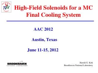
Challenges inHigh Field Solenoids A. Hervé / ETHZ CLIC09-Workshop,13 October 2009
Coil tested in August 2006 I will use the CMS coil as an example Alain Hervé, CLIC08 Workshop, 16 October 2008
CMS superconducting coil Alain Hervé, CLIC09 Workshop, 13 October 2009
Magnet tested on Surface in August 2006(Here we show stresses in Cold Mass) • Von Mises stress measured at 4T : 138 MPa • Complete agreement with computation of 1998. 0.2% is conventional elastic limit of aluminum alloys! Alain Hervé, CLIC09 Workshop, 13 October 2009
Temperature rise after fast-dump on dump resistors is ≠ 70 K Temperature rise up to 70 K 1 hour Pressure rise in PS 50% of energy is extracted This is to not induce dangerous thermal stresses in the coil. If no energy is extracted Tmean ≈130K! Alain Hervé, CLIC09 Workshop, 13 October 2009
CLIC09 Workshop 13 October 2009 Review of the Design Options Parametersretained for the coilin the early 1990s Alain Hervé, CLIC09 Workshop, 13 October 2009
1990: 1.5-T ALEPH* taken as demonstrator • NbTi Rutherford cable, pure aluminum stabilization, Enthalpy Stability Temperature Margin ≈ 1.8 K • External mandrel for indirect cooling by thermo-siphon, inner winding, potted under vacuum with fiber-glass/epoxy resin • Use external mandrel for a passive protection scheme based on the quench-back effect • In case of fast dump, extract 50% of the energy in a dump resistor and keep thefinal temperature of the cold mass ≈ 70 K • Allow, as ultimate case, 100% of the energy in the cold mass accepting to reach 130 K a few times during the lifetime of the coil * J.M. Baze, H. Desportes et al., Design Construction and Test of the Large Superconducting Solenoid ALEPH, IEEE. Trans Magn. Vol 24, 1988 Alain Hervé, CLIC09 Workshop, 13 October 2009
Additional parameters due to increased B0 • Large 20 kA conductor, four-layer winding, and five modules • Magnetic pressure of 64 bars, thus:high-strength aluminum alloy is required Founding assumption of CMS (J.C. Lottin) was to position this alloy directly on the conductor • Hoop strain reaches 0.15%, “von Mises strain”must stay < 0.2% A large 12’000-ton axial magnetic compressive force has to be transmitted from module to module • Stored magnetic energy 2.6 GJ, the specific ratio E/M reaches 11.6 kJ/kg of cold mass Alain Hervé, CLIC09 Workshop, 13 October 2009
E/M ratio vs E for several solenoids E/MinkJ/kgofcoldmass This ‘anomalous’ positioning meant that innovative solutions were needed to face this challenge Stored Magnetic Energy in MJ Alain Hervé, CLIC09 Workshop, 13 October 2009
Critical Review of Main Design Choices • It is interesting to critically review the design choices made by the Design Team to meet this challenge • Then examine the possibilities of increasing the central field to 5T using the same technology (For example recent proposals for ILC and CLIC use 4T and 5T coils building on CMS principles) Alain Hervé, CLIC09 Workshop, 13 October 2009
CLIC09 Workshop 13 October 2009 Review of the Design OptionsMain challengesthat the design team had to face in the early 1990s Alain Hervé, CLIC09 Workshop, 13 October 2009
Main design and construction challenges Sc 1. Extrude a large section NbTi Al stabilized conductor 2. Obtain a compound reinforced conductor with the necessary mechanical strength M 3. Build precise mandrels although they cannot be stress relieved M M 4. Wind precise layers using a very stiff conductor 5. Limit shear stress on insulation inside the coil in particular in between two modules M 6. Insert a 220-t coil inside a vacuum vessel having an horizontal axis M 5 challenges out of 6 were mechanical challenges! Alain Hervé, CLIC09 Workshop, 13 October 2009
CMS Reinforced Conductor continuous aluminum alloy sections added to“standard” conductor32 strands => Temperature Margin 1.8K Alain Hervé, CLIC09 Workshop, 13 October 2009
Each layer is supported by its ‘own’ mandrel Thermosiphon cooling Mandrel 50mm After curing reinforcements create criss-crossedmatricesmimickingperfectly fitting individual mandrels Mandrel 4 Layer 4 Mandrel 3 Layer 3 Mandrel 2 Layer 2 Mandrel 1 Layer 1 Mandrel 0 Coil Axis Alain Hervé, CLIC09 Workshop, 13 October 2009
Choice of Reinforcing Alloy AA 6082 T6 has been chosen, (hard temper T6 obtained after curing cycle of the coil) This allows winding with a not too stiff conductor! Alain Hervé, CLIC09 Workshop, 13 October 2009
Evolution of AA 6082 during process Spools of reinforcement are received as under-aged stabilized temper T51 Alain Hervé, CLIC08 Workshop, 16 October 2008
CLIC09 Workshop 13 October 2008 Can the Basic Element of the CMS Coil Concept: the Reinforced Conductor,be Improved to Reach 5T? Alain Hervé, CLIC09 Workshop, 13 October 2009
Load Line of the CMS Cable Bnom=4T, Inom(4T)=19.3kA, Toper=4.5K, Bmax=4.6T Alain Hervé, CLIC09 Workshop, 13 October 2009
CMS Cable for a 5T Coil (Bmax = 5.75 T) Need 83Strands!!! 1.8K Cablingmachine limited to40 strands40/32=1.25 Need 54Strands! 1.5K 1.25 = 40 strands = 1.25 K Still 1Kat B0 = 5T Alain Hervé, CLIC09 Workshop, 13 October 2009
CMS Cable for a 5T Coil (Bmax = 5.75 T) If thenominal current isreduced to14625 Aa Tempmargin of 1.5 Kcan beobtainedwith32 strands Alain Hervé, CLIC09 Workshop, 13 October 2009
40 strand Cable for a 5T Coil (Bmax = 5.75 T) If thenominal current isreduced to18286 Aa Tempmargin of 1.5 Kcan beobtainedwith40strands Alain Hervé, CLIC09 Workshop, 13 October 2009
Properties of pure aluminum in CMS coiland effect of ageing In additionpure aluminumdoes notparticipateto the mechanical strength Ageing Magnetoresistance 400! Can we use a more adapted stabilizer, with RRR around 400with better mechanical properties? Alain Hervé, CLIC09 Workshop, 13 October 2009
Stored Energy/per unit length of cold mass Alain Hervé, CLIC09 Workshop, 13 October 2009
CMS parameters and what can be varied? Alain Hervé, CLIC09 Workshop, 13 October 2009
B0 and r do not appear in the formula Thus there is nothing magic with B0 or r! However, B0 and r are not without influence on difficulties and cost! Not forgetting the cost of the return yokeif one wants to limit the stray field! Alain Hervé, CLIC09 Workshop, 13 October 2009
Thus Properties of CMS Alloys at 4.2 K are sufficient because strain < 0.2%! For hoop strain 0.15 % von Misesstrain < 0.2% Also just OK for weldments ! Alain Hervé, CLIC09 Workshop, 13 October 2009
12 kJ/kg with α = 0.6 -> σvon Mises = 140 MPa -> σel = 210 MPa -> σult = 420 MPa Alain Hervé, CLIC09 Workshop, 13 October 2009
Advantages of an Improved Conductor Alain Hervé, CLIC09 Workshop, 13 October 2009
CLIC09 Workshop 13 October 2009 Conclusion Alain Hervé, CLIC09 Workshop, 13 October 2009
Conclusion-I • NbTi cable extruded in a stabilizer is applicable up to 5 Tesla, maintaining a stability margin of 1.5 K (32 strands -> 40 & 18200 A) • There is a risk in increasing the temperature of cold mass after a fast dump over 70 K (130 K in emergency situation) • It seems difficult to design for a hoop strain exceeding 0.15 %,(0.2% wrt. von Mises stress) respecting construction codes • It seems impossible to construct thick mandrels with the needed mechanical properties Thus the use of reinforced conductor still seems a good solution, Alternatively use a mechanically resistant stabilizer With σel ≈ 210 MPa and σult ≈ 420 MPa, ε > 10%. Alain Hervé, CLIC09 Workshop, 13 October 2009
Conclusion-II • Increasing the field means increasing the amount of material to create the ampere-turns and limit the hoop-strain, for example 6 layers for 5T compared to 4 layers for 4T • This added material will keep the ratio E/M at 12 kJ/kg of cold mass, thus respecting the 70K limit after a fast dump • Aluminum Alloys 5083-H351 for the mandrels and 6082-T6 for the reinforcement are directly usable • The replacement of the pure aluminum stabilizer by cold drawn Al-0.1wt%Ni alloy* would allow increasing the mechanical performance of the conductor, and stay in a nearly fully elastic state* A. Yamamoto et al. Alain Hervé, CLIC09 Workshop, 13 October 2009
Conclusion-III The CMS design would suit any new 3.5 or 4-Tesla coil. A 5-Tesla large thin coil, respecting all parameters considered safe today, would be a natural extrapolation of the CMS design, with the possible use of an improved conductorusing cold drawn Al-0.1wt%Ni alloy as stabilizeror a mechanically highly resistant stabilizer. Alain Hervé, CLIC09 Workshop, 13 October 2009
Conclusion-IV Reaching 5T requires to launch an R&D program to: • Check possibility of using “Yamamoto’s alloy” in a reinforced conductor à la CMS, and find an easier and less expensive technique to replace EB welding to attach the reinforcement. • Or find a mechanically highly resistant stabilizer • In all cases it is important to secure a safe industrial solution for the co-extrusion of the sc cable. Alain Hervé, CLIC09 Workshop, 13 October 2009