Download
1 / 24
240 likes | 398 Views
1 mm Polarization Science with CARMA. Chat Hull Collaborators: Dick Plambeck , Greg Engargiola , & all the CARMA staff 19 August 2011 URSI General Assembly XXX Istanbul, Turkey.

E N D
1 mm Polarization Science with CARMA Chat Hull • Collaborators: Dick Plambeck, Greg Engargiola, & all the CARMA staff 19 August 2011 • URSI General Assembly XXX • Istanbul, Turkey
CARMACombine Array for Research in Millimeter-wave AstronomyConsortium: Berkeley, Caltech, Illinois, Maryland, Chicago • Attributes • 6 ⨯10-m, 9 ⨯ 6-m, 8 ⨯ 3.5-m telescopes • Observations at 1mm, 3mm, and 1cm • Located in Cedar Flat, CA (near Bishop) • Science goals • Molecular emission in galaxies • Galaxy clusters • Protoplanetary debris disks • Dust polarization in star-forming regions
Class 0 Dust Polarization Credit: NASA, ESA, STScI,J. Hester and P. Scowen (Arizona State University)
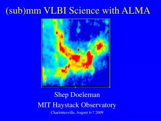
Credit: Bill Saxton, Harvard-Smithsonian Center for Astrophysics
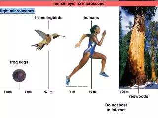
Why observe polarization? • B-fields play an important role in star formation • How important? • Are they strong (& ordered)? • Are they weak (& chaotic)? • B-fields polarization • Dust grains align their spin axes with B-fields • Dust emission is strong at 1 mm
First Target: NGC 1333 IRAS 4A CARMA observations SMA observations Girart+ 2006 • We want to search for “hourglass” shape of the B-field structure in the circumbinaryenvelope
How do we make it work? Grad student
1 mm Dual-polarization Receivers SIS mixers Orthomode transducer Waveguide circular polarizer WBA13 I.F. amplifiers (1-9 GHz) 1 inch
Turnstile-junction OMT 1 cm Navarrini & Plambeck 2006, IEEE-MTT, 54, 272-277
Unequal sidearm lengths in OMT can cause resonances (simulation)
OMT tests at 4K(passbands, LO = 210-255 GHz in 1 GHz steps) OMT15 (good) OMT10 (bad)
Polarizer construction Copper electroplated onto mandrel Aluminum mandrel Machined Soldered into waveguide flange 1 inch
Final design: 2-section polarizer λ/2 retarder at 15° λ/4 retarder at 74.5° 0.047’’ diameter facets 0.006’’ deep
XY RL Sky Receiver
Sample polarizer test data(mandrel machining errors) Fraction of linear radiation converted to RCP and LCP
Polarization calibration • Two main steps to calibrate a polarimeter: • XY phase • The absolute phase offset between the RCP and LCP receivers of an antenna • Leakage terms • The fraction of LCP radiation detected in the RCP receiver, and vice versa
XY phase calibration • How do we find an antenna’s XY phase? • Observe a strongly polarized source with known position angle • These don’t exist at mm wavelengths • We create our own by observing broadband noise from the ambient load through a wire-grid polarizer!
XY phase calibration SKY (~60 K) WIRE-GRID POLARIZER AMBIENT LOAD (300 K) FEED HORN
RF = 210 – 270 GHz IF = 1 – 9 GHz Baseband = 0.5 – 1.0 GHz τ2 1 mm signal path τ1 τ3,hi 10 GHz mixer Baseband mixer RF mixer 1– 5 GHz 5 – 9 GHz To digitizer, filter, & correlator 0.5 – 1.0 GHz 1 – 9 GHz RCP τ4 τ3,lo 1– 5 GHz LO 2 NOISE FILTER FILTER FILTER FILTER FILTER FILTER Feed horn Polarizer 1.75 – 4.25 GHz Correlated Noise Source All phases flat OMT Block downconverters 8-way splitters 1– 5 GHz 5 – 9 GHz To digitizer, filter, & correlator 0.5 – 1.0 GHz LCP 1 – 9 GHz 1– 5 GHz
Status/conclusions • Dual-polarization receivers are installed on all 15 6- and 10-m telescopes • Full-Stokes (LL, LR, RL, RR) system is working • Observed NGC 1333-IRAS 4A as a commissioning test • XY phase offset is well understood • Leakages need to be determined better • Will soon install new Berkeley-made polarizers • Full-Stokes commissioning time will be in Oct., 2011