Download
1 / 15
150 likes | 287 Views
DOS Protected Mode Interface ( DPMI ). Harsh alkutkar. AN INTRODUCTION TO WHY WE USE DPMI. The 8088 CPU used in the original IBM PC was not very scalable. In particular, there was no easy way to access more than 1 megabyte of physical memory.

E N D
DOS Protected Mode Interface (DPMI) Harsh alkutkar
AN INTRODUCTION TO WHY WE USE DPMI • The 8088 CPU used in the original IBM PC was not very scalable. In particular, there was no easy way to access more than 1 megabyte of physical memory. • To get around this while allowing backward compatability, • Intel designed the 80286 CPU with two modes of operation: • Real mode, in which the '286 acts like a fast 8088, • and protected mode (now called 16-bit protected mode).
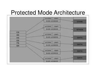
PROTECTED MODE • Protected mode allows programs to • 1) access more than 1 megabyte of physical memory, and • 2) protects against misuse of memory (i.e. programs can't execute a data segment, or write into a code segment). • An improved version, 32-bit protected mode, first appeared on the '386 CPU.
I thought protected mode didn't use segmented memory? • The segments are still there, but in 32-bit protected mode, you can set the segment limit to 4G bytes. This is • the maximum amount of physical memory addressable by a CPU with a 32-bit address bus. Limit-wise, the • segment then "disappears" (though other protection mechanisms remain in effect). This reason alone makes • 32-bit protected mode popular.
What's a descriptor? • In real mode, there is little to know about the segments. Each is 64K bytes in size, and you can do with the segment what you wish: store data in it, put your stack there, or execute code stored in the segment. • The base address of the segment is simply 16 times the value in one of the segment registers. • In protected mode,besides the segment base address, we also need the segment size (limit) and some flags indicating what the segment is used for. This information goes into an 8-byte data structure called a descriptor:
Structure of Descriptor • Code/Data Segment Descriptor Table
Meaning of bits • Present bit. Must be set to one to permit segment access. • Privilege. Zero is the highest level of privilege (Ring 0), three is the lowest (Ring 3). • Executable bit. If one, this is a code segment, otherwise it's astack/data segment. • Expansion direction (stack/data segment). If one, segment grows downward, and offsets within the • segment must be greater than the limit. • Conforming (code segment). Privilege-related. • Writable (stack/data segment). If one, segment can be written to. • Readable (code segment). If one, segment can be read from. (Code segments are not writable.) • Accessed. This bit is set whenever the segment is read from or written to.
Where are the descriptors? • They are stored in a table in memory: • the Global Descriptor Table (GDT), • Interrupt Descriptor Table (IDT), • or one of the Local Descriptor Tables. • The CPU contains three registers: GDTR, which must point to the GDT, • IDTR, which must point to the IDT (if interrupts are used), and LDTR, which must point to the LDT (if • the LDT is used). • Each of these tables can hold up to 8192 descriptors.
Loading DPMI Clients and Extended Applications • All DPMI applications begin execution in real mode. An application must run first as a standard real mode DOS program but it can switch to protected execution by making a few simple calls. • DPMI does not define an executable file format for protected mode programs. Instead, programs must provide their own mechanism for loading and fixing up protected mode code.
There are two parts to DPMI code • Obtaining the Real to Protected Mode Switch Entry Point • Calling the Real to Protected Mode Switch Entry Point
Obtaining the Real to Protected Mode Switch Entry Point • This function can be called in real mode to detect the presence of DPMI services and to obtain an address that can be used to begin execution in protected mode. • To Call • AX = 1687h • Execute an Int 2Fh (not an Int 31h) • Returns • If function was successful: AX = 0 BX = Flags Bit 0 = 1 • if 32-bit programs are supported • CL = Processor type 02h = 80286 03h = 80386 04h = 80486 • DH = DPMI major version number • DL = DPMI minor version number • SI = Number of paragraphs required for DPMI host private data (may be 0) • ES:DI = Address of procedure to call to enter protected mode If function was not successful: AX != 0 • Programmer's Notes • This function does not perform the actual transition into protected mode. You need to call the address returned in ES:DI, after allocating the private data area for the DPMI host, to perform the actual real to protected mode switch.
Calling the Real to Protected Mode Switch Entry Point • After using Int 2Fh function 1687h, to obtain the protected mode entry point, the DPMI client must call the entry point address as described in this section. • To Call • AX = Flags • Bit 0 = 1 if program is a 32-bit application • ES = Real mode segment of DPMI host data area. This must be the size of the data area returned in SI from the previous function. • ES will be ignored if the required data size is zero. • Call the address returned in ES:DI by the previous function • ReturnsIf function was successful: Carry flag is clear. • Program is now executing in protected mode. • CS = 16-bit selector with base of real mode CS and a 64K limit • SS = Selector with base of real mode SS and a 64K limit • DS = Selector with base of real mode DS and a 64K limit • ES = Selector to program's PSP with a 100h byte limit • FS and GS = 0 (if running on an 80386 or 80486) If the program is a 32-bit application the high word of ESP will be 0 • All other registers are preserved If function was not successful: Carry flag is set. Program is executing in real mode