Download
1 / 10
100 likes | 215 Views
ENDURANCE TESTS for PTFE CATALYST. National Institute of Cryogenics and Isotope Technologies ICSI Rm. Valcea Romania M. Vladu, S Brad, F. Vasut, M. Vijulie, M. Constantin. BRIEF DESCRIPTION OF THE TASK DELIVERABLES. WDS – the key systems to control the tritium contents

E N D
ENDURANCE TESTS for PTFE CATALYST National Institute of Cryogenics and Isotope Technologies ICSI Rm. Valcea Romania M. Vladu, S Brad, F. Vasut, M. Vijulie, M. Constantin
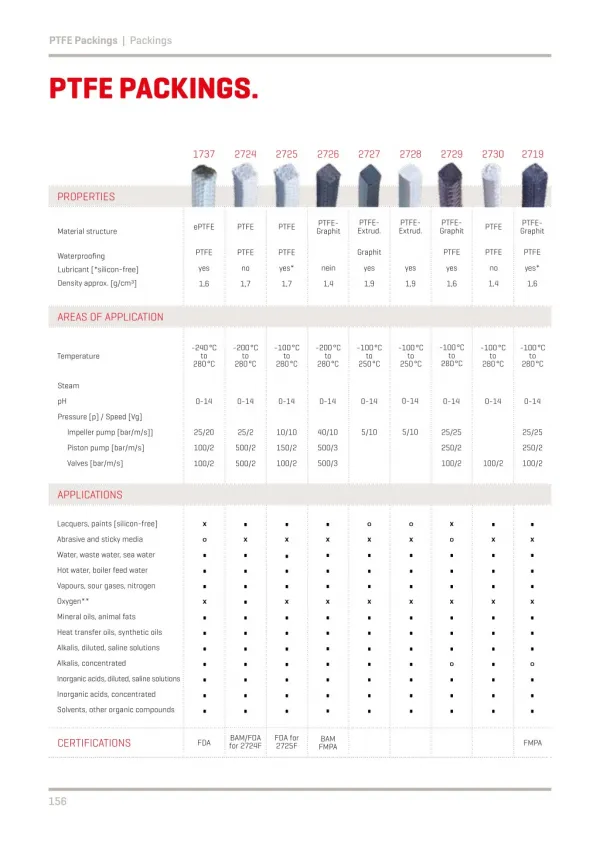
BRIEF DESCRIPTION OF THE TASK DELIVERABLES • WDS – the key systems to control the tritium contents • Expanding the FZK tests • Catalyst based on platinum material and charcoal support The degradation of the WDS catalyst will strongly affect its separation performances and consequently will increase the tritium releases into the environment. If a catalyst based on Teflon material will be used for the LPCE column of WDS, the fluoride that may be released as an effect of tritium environment causes the corrosion of the LPCE column with unpredictable effects. Therefore the quantification of catalyst degradation and the amount of fluoride released is needed for planning the maintenance activities and to predict the operation life time of the WDS components
Technology The main parts of the experimental stand are: • Process pump – Bran+Luebbe process pump for tritiated water; • Catalyst Pt/C/PTFE column; • Tritiated water vessel; • Electric heater; • Water heater; • Normal water pump • Tritiated and normal water filling trap; • Draining system. The experimental setup at ICIT Rm. Valcea, for this task TW6-TTFD-TR64, consists in a small LPCE column filled with the same type of catalyst as in the TLK LPCE column. The column will be in operation for one year with tritiated water of 100 Cikg-1. For the experiments ICIT Rm.Valcea manufacture the necessary hydrophobic catalyst.
Design Basis The tritiated water (100Ci/L) is filled up in the vessel V1. The normal water is filled in the vessel V2 The normal water enters through the bottom of the column jacket and get out from the upper part and filled the V2 vessel. Pump P2 circulates the normal water from vessel V2 through the H101 heater to the column jacket, and the cycle is repeating. From vessel V1, the tritiated water is circulating by the P1 pump, through the heating coil from vessel V2 into the LPCE column. The tritiated water temperature is measured in three points, at the inlet, middle and outlet of the column. If the medium temperature, obtained from these three measurements, is different than 80 Celsius degree, the temperature feedback control loop decrease/increase the power supply to the regulating resistance from H101.
Technology • The catalyst was made by mixing politetrafloroethylene with platinum charcoal, then manufacturing like pellets with 2,5 mm diameter and 15 mm length. The concentration of platinum in the catalyst is 2%.
Technology Images of platinum catalyst on charcoal in the SEM (Scanning Electron Microscopy) From the Scanning Electron Microscopies we can notice that the platinum particles dimensions are in the range of tens or hundred of microns, the pores are in the same size range. In comparison with the results obtained through the X-ray diffraction technique, we can conclude that the platinum particles contain numerous crystallites.
Technology ICIT contribute to this task by exploring improvements in the manufacturing process for catalysts to be used in the water detritiation process: - New catalysts. Based on the experience in the field of hydrophobic catalysts used in isotopic exchange reaction, ICIT produce and characterize new types of catalysts. - New catalyst manufacturing techniques. Taking into account the properties of the proposed metallic oxides (hydrophobic and binding properties), new manufacture techniques will be designed and developed. - Catalysts testing. The testing activity will be focused on endurance tests to evaluate the influence of tritium on catalyst properties. Then, a suitable catalysts regeneration procedure shall be developed.
Technology - Work related to these topics belongs to the task TW6-TTFD- (Art.5.1a) from the EFDA Technology Work Program 2006 and was done in collaboration with Horia Hulubei National Institute of Physics and Nuclear Engineering (IFIN – HH). - Part of this work has been performed during the Mobility Secondment at Forshungszentrum Karlsruhe – Tritium Laboratory, Germany.
Conclusion Isotopic exchange catalyst’s stability was analyzed by: • evaluating the absorbed dosed in tritiated water solutions • simulating by quanto-chemical methods the isotopic exchange catalysts’ behaviour, which were exposed to tritiated water. Radio-chemical yields determination • stimulating radiolytic processes by exposing the catalyst which was immersed in water to a gamma radiation field • studying the behaviour of the isotopic exchange catalyst in presence of tritiated water. The results obtained by mathematical moulding show an exposure to very high doses of the superficial layer of the isotopic exchange catalyst for contact periods exceeding 30 days. The determined absorbed doses a lot higher than the stability limit of the PTFE polymers (0,3 MGy). The analysis of the primary and secondary radiolytic processes by quanto-chemical simulations shows different degradation mechanisms, associated with similar effects, respectively: • the break up of the main polymeric bound and • the HF significant emission