Download
1 / 45
460 likes | 584 Views
Ch. 3-1 CPU. Input and output. Supervisor mode, exceptions, traps. Memory management and address translation Caches CPU Performance and power consumption Co-processors. I/O devices. Usually includes some non-digital component Disk drive => rotaing disk + analog read/write electronics

E N D
Ch. 3-1 CPU • Input and output.Supervisor mode, exceptions, traps.Memory management and address translationCachesCPU Performance and power consumptionCo-processors.
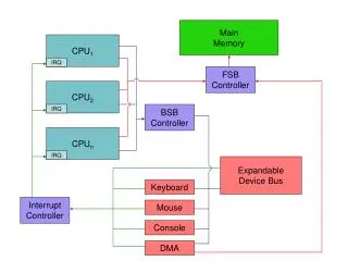
I/O devices • Usually includes some non-digital component • Disk drive => rotaing disk + analog read/write electronics • Typical digital interface to CPU: Information about device operation status reg CPU Device mechanism data reg
Application: 8251 UART • Universal asynchronous receiver/transmitter (UART) : provides serial communication. • 8251 functions are integrated into standard PC interface chip (today). • Allows many communication parameters to be programmed.
Serial communication • Data are transmitted as streams of characters, separately: no char bit 0 bit 1 bit n-1 ... stop start time • Start bit: used to recognize the start of a new character • Stop bit: indicates a transition • Data bit: high or low voltage • Baud rate: the inverse of the one bit period
Serial communication parameters • Baud (bit) rate. • Number of bits per character (5 thru 8). • Parity/no parity. • Even/odd parity. • Length of stop bit (1, 1.5, 2 bits).
8251 CPU interface status (8 bit) CPU xmit/ rcv data (8 bit) serial port • Transmitter Ready: transmitter is ready to accept a data character • Transmitter Empty signal goes high • Receiver Ready: goes high when the UART has a character to be read by CPU
Programming I/O • Two types of I/O Mechanisms • I/O Instructions (ex. x86) • Special-purpose I/O instructions (IN/OUT instructions in x86); • Separate address space for I/O devices • Memory-mapped I/O (ex. ARM) • Normal read/write instructions (LDR/STR instrcutions in ARM) • Addresses for the registers in each I/O device • Most CPUs use memory-mapped I/O. • I/O instructions do not preclude memory-mapped I/O.
ARM memory-mapped I/O • Define location for device: DEV1 EQU 0x1000 • Read/write code: LDR r1,#DEV1 ; set up device adrs LDR r0,[r1] ; read DEV1 LDR r0,#8 ; set up value to write STR r0,[r1] ; write value to device
SHARC memory mapped I/O • Device must be in external memory space (above 0x400000). • Use DM to control access: I0 = 0x400000; M0 = 0; R1 = DM(I0,M0);
Peek and poke • Traditional HLL interfaces: int peek(char *location) { return *location; // de-reference location pointer } void poke(char *location, char newval) { (*location) = newval; } #define DEV1 0x1000 … dev_status = peek(DEV1); #define DEV1 0x1000 … poke(DEV1, 8);
Busy/wait IO • Simplest way to program device (polling). • Use instructions to test when device is ready. #define OUT_CHAR 0x1000 // output device character register #define OUT_STATUS 0x1001 // output device status register char *mystring = “Hello, world.” char *current_char; current_char = mystring; // point to head of string while (*current_char != ‘\0’) { poke(OUT_CHAR,*current_char); //send character to device //ouput status register becomes 1 while (peek(OUT_STATUS) != 0); // keep checking status current_char++; }
IN_DATA REG IN-STATUS_REG CPU Device mechanism OUT_DATA REG OUT-STATUS_REG Simultaneous busy/wait I/O • Copying characters from input to output using busy-wait I/O #define IN_DATA 0x1000 #define IN_STATUS 0x1001 #define OUT_DATA 0x1100 #define OUT_STATUS 0x1101 /* The input device set its status register to 1 when a new char has been read. */ while (TRUE) { /* read */ while (peek(IN_STATUS) == 0); // wait until ready achar = (char)peek(IN_DATA); poke(IN_STATUS,0); /* write */ poke(OUT_DATA, achar); poke(OUT_STATUS,1); //turn on device while (peek(OUT_STATUS) != 0); //wait until done }
Interrupt I/O • Busy/wait is very inefficient. • CPU can’t do other work while testing device. • In fact, CPU should be able to do some other computations or control of other devices. • Hard to do simultaneous I/O. • Interrupts allow a device to change the flow of control in the CPU. • Causes subroutine call to handle device.
Interrupt interface intr request status reg CPU intr ack Device mechanism IR PC data/address data reg
Interrupt behavior • Based on subroutine call mechanism. • Interrupt forces next instruction to be a subroutine call to a predetermined location. • Return address is saved to resume executing foreground program.
Interrupt physical interface • CPU and device are connected by CPU bus. • CPU and device handshake: • device asserts interrupt request; • CPU asserts interrupt acknowledge when it can handle the interrupt.
Example: character I/O handlers void input_handler() { achar = peek(IN_DATA); gotchar = TRUE; poke(IN_STATUS,0); } void output_handler() { }
Example: interrupt-driven main program main() { while (TRUE) { if (gotchar) { poke(OUT_DATA, achar); poke(OUT_STATUS, 1); gotchar = FALSE; } } }
a head head tail tail Example: interrupt I/O with buffers • Queue for characters: head
Buffer-based input handler #define IN_DATA 0x1000 #define IN_STATUS 0x1001 void input_handler() { char achar; if (full_buffer()) error = 1; else { achar = peek(IN_DATA); add_char(achar); } // set status register back to 0 poke(IN_STATUS,0); // if buffer was empty, start a new output transaction. if ((peek(OUT_StATUS)==0) && (nchars() == 1)){ poke(OUT_DATA, remove_char()); poke(OUT_STATUS,1); } } #define OUT_DATA 0x1100 #define OUT_STATUS 0x1101 void output_handler() { if (!empty_buffer() { poke(OUT_DATA,remove_char()); poke(OUT_STATUS, 1); } }
I/O sequence diagram :foreground :input :output :queue empty a empty b bc c
Debugging interrupt code • What if you forget to change registers? • Foreground program can exhibit mysterious bugs. • Bugs will be hard to repeat---depend on interrupt timing. • What if interrupt handler (read_handler)changes the value j? (Example 3-7) // y = Ax + b for (i=0; i <M; i++) { y[i] = b[i]; for (j=0; j<N; j++) y[i] = y[i] + A[i,j]*x[j]; } }
Priorities and vectors • Two mechanisms allow us to make interrupts more specific: • Priorities determine what interrupt gets CPU first. • Vectors determine what code is called for each type of interrupt. • Mechanisms are orthogonal: most CPUs provide both.
Interrupt acknowledge log2n device 1 device 2 device n L1 L2 ... Ln CPU Prioritized interrupts
Interrupt prioritization • Masking: interrupt with priority lower than current priority is not recognized until pending interrupt is complete. • Non-maskable interrupt (NMI): highest-priority, never masked. • Often used for power-down.
Example: Prioritized I/O :interrupts :foreground :A :B :C B C A A,B A has the highest priority
Interrupt vectors • Allow different devices to be handled by different code. • Interrupt vector table: Interrupt vector table head handler 0 handler 1 handler 2 handler 3
Interrupt vector acquisition :CPU :device Device Vector Receive Int request Interrupt ACK Interrupt request receive ACK (vector number) Receive Int vector CPU Hardware Structure
Generic interrupt mechanism continue execution intr? N Assume priority selection is handled before this point. Y N ignore intr priority > current priority? Y Send Ack N Y N bus error timeout? Get vector? Y call table[vector]
Interrupt sequence • CPU acknowledges request. • Device sends vector. • CPU calls handler. • Software processes request. • CPU restores state to foreground program.
Sources of interrupt overhead • Handler execution time. • Interrupt mechanism overhead. • Register save/restore. • Pipeline-related penalties. • Cache-related penalties.
ARM interrupts • ARM7 supports two types of interrupts: • Fast interrupt requests (FIQs). • Interrupt requests (IRQs). • An FIQ takes priority over an IRQ • Interrupt table starts at location 0.
ARM interrupt procedure • CPU actions: • Save PC • Copy CPSR to SPSR_irq or SPSR_fiq. • Force bits in CPSR to record interrupt. • Force (set) PC to interrupt vector. • Handler responsibilities when leaving interrupt handler: • Restore proper PC. • Restore CPSR from SPSR_irq or SPSR_fiq. • Clear interrupt disable flags.
ARM interrupt latency • Worst-case latency to respond to interrupt is 27 cycles: • Two cycles to synchronize external request. • Up to 20 cycles to complete current instruction. • Three cycles for data abort. • Two cycles to enter interrupt handling state.
SHARC interrupt structure • SHARC supports vectored, prioritized, maskable interrupts. • Priorities are fixed: reset highest, user SW interrupt 3 lowest. • Vectors are also fixed. • Vector is offset in vector table. Table starts at 0x20000 in internal memory, 0x40000 in external memory
SHARC interrupt sequence Start: must be executing or IDLE/IDLE16. 1. Output appropriate interrupt vector address. 2. Push PC value onto PC stack. -- Depending on the type of interrupt, may push ASTAT and MODE1 registers onto the status stack 3. Set bit in interrupt latch register (IRPTL). 4. Set IMASKP to current nesting state.
SHARC interrupt return Initiated by RTI instruction 1. Pop PC stack into PC. Return to address at top of PC stack. 2. Pop status stack if appropriate. 3. Clear bits in interrupt latch register and IMASKP.
SHARC interrupt performance Three stages of response: • 1 cycle: synchronization and latching; • 1 cycle: recognition; • 2 cycles: branching to vector. Total latency: 4 cycles.
Supervisor mode, Exceptions, and Traps • Similar to interrupts • Supervisor mode handles exceptional events and protect executing programs
Supervisor mode • May want to provide protective barriers between programs. • Avoid memory corruption. • Need supervisor mode to manage the various programs. • Ex) Control of MMU is typically reserved for supervisor mode. • SHARC does not have a supervisor mode.
ARM supervisor mode • Use SWI instruction to enter supervisor mode, similar to subroutine: SWI CODE_1 • Sets PC to 0x08. • Argument to SWI is passed to supervisor mode code. • Saves CPSR in SPSR_svc.
Exception • Exception: internally detected error. • Ex) Division by zero • Exceptions are synchronous with instructions but unpredictable. • Build exception mechanism on top of interrupt mechanism. • Exceptions are usually prioritized and vectorized.
Trap • Trap (software interrupt): an exception generated by an instruction. • Enter supervisor mode. • But must be controlled to maintain security. • ARM uses SWI instruction for traps. • SHARC offers four levels of software interrupts. • Called by setting one of the bits in IRPTL register.
Co-processor • Co-processor: added function unit that is called by instruction. • Floating-point units are often structured as co-processors. • ARM allows up to 16 designer-selected co-processors. • Ex) Floating-point unit • Provides 80-bit fp data registers and fp status registers. • This unit occupies two floating-point co-processor units, numbered 1 and 2.