Download
1 / 36
380 likes | 573 Views
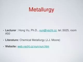
Physical Metallurgy 25 th Lecture. MS&E 410 D.Ast dast@ccmr.cornell.edu 255 4140. IC Metallization. 6 level Cu metallization (IBM). Interlayer dielectrics etched away. SEM picture with fake color. Disclaimer

E N D
Physical Metallurgy25 th Lecture MS&E 410 D.Ast dast@ccmr.cornell.edu 255 4140
IC Metallization 6 level Cu metallization (IBM). Interlayer dielectrics etched away. SEM picture with fake color
Disclaimer This is an exceedingly complex topic of which has, because of its importance, studied in nearly unbelievable detail. It is likely that we know more about the metallurgy of IC metals than about the metallurgy of steels. Metallization, more than transistor size, controls the density to which we can pack transistor on a chip and the speed of the IC. Thus, we can only skim the surface… the topic could easily fill an entire semester !
Outline • We will follow history… • Aluminum metallization • =>Al spiking => Al-Si alloys • =>Diffusion barriers in Al metallization • => Electromigration • Silicide based metallization (short haul) • Planarity control => Increasing # of interconnects • Cu metallization
Al metallization • Late 80’s 2 level Al metallization (DRAM) • S/D contact with silicide • W plug to M1 (Al) • W plug to M2 Al (as discussed before) adheres well to Si when annealed at ~ 400C because it reduces the native oxide to an Al sub-oxide. The resistivity of Al second lowest of non-precious metals
Neither Au, Cu or Ag adhere well => low formation energy for oxides. Au,Cu and Ag all are fast interestitial diffusers and generate recombination centers in the band gap. Aluminum is a slow, substitutional diffuser Aluminum is a p-type dopant
With shallower S/D junctions the pitting problem appeared Heavily doped p+ spike penetrates n+ drain contact and shortens p type channel to drain contact During contact anneal, Si dissolves in Al, and returns, during cooling as p+ doped Si
Al can dissolve up to 1.5 at% Si. Cure: Add Si to Al metal but resistivity (alloy scattering) increases
Solubility is one aspect, diffusion is the other Si can diffuse tens of microns along Al lines. At 3E-9 cm2/sec the diffusion distance for 10 minutes is 13 mm. Consequently, a large (by IC standard) volume is available
The problem of spiking let to the development of the silicide contact. A silicide is an Si-Metal compound with near metallic conductivity. The thin silicide layer separates the n+ doped source and drain from the Al. The silicide has to be stable in contact with Al, more later
The “best” silicides have resistivities of 15 mW-cm which is 6 times that of Al. Since the silicide a very small fraction of the interconnect, its influence on the resistance is negligible. “best” is in brackets because more the resistivity goes into this selection
Silicides are formed by depositing the metal onto the Si and heating. The metal richest phase typically appears first, followed by less metal rich phases until the least metal containing silicide is reached.
This is a most remarkable sequence which you would never expect from the phase diagram. And it takes place at temperatures well below the lowest eutectic temperatures ! With a planar interface !!!! The reaction sequence is specific to thin metal films on a surplus of silicon and entirely kinetically controlled (eventually all explained by Goesele). Self-test: Which silicide would you expect from the phase diagram ?
The silicide is in contact with Al. Is this a stable situation ?
In the case of the much studied* Pd2Si = > no 3Al + 4PdSi => Al3Pd4Si + 3Si Al3Pd4Si is stable (has tie lines with) in contact with Pd2Si (as well as PdSi) as well as Si. But it is unstable against Al. Continuous reactions form Al-Pd compounds. To surpress this, a diffusion barrier of TiN is often inserted between the Pd2Si and the Al. * much studied because it makes a high work function Schottky diode against low doped Si
Electromigration The silicide Al metallization continued until the mid 90’s when electromigration problem and planarization problem impeded further progress along Moore’s law for CPU’s Early electro- migration failure. Note that it occurs only at selected spots of the metal line.
You can read statements such as Which would predict that time to 50% of lines failed t50 = Constant J-1 Do exp(-EA/kT)
In reality, one finds t50 = Constant J-2…3 Do exp(-EA/kT) Indicating that electromigration is a more complex problem, more later. Emperically, one found that the addition of small amounts of Cu to the Al-Si alloy greatly increased the time to failure. Failure followed a log-normal distribution where t50 and s are adjustable parameters and f(t) is the probability (for failure) density function
Adding 4 wt% Cu increased the time to failure by 2 orders of magnitude, good enough as computers are obsolete in a few years :-)
Electromigration, Key Points • Forming of voids and hillocks as result of current flow • Discovered as IBM machines failed during operation at customer sites. • Electron energy (< 5 eV, at Fermi surface) insufficient to dislodge atoms from lattice (Ed ~ 20 eV). • Electron energy sufficient to influence atom at saddle point during self-diffusion. • Self-diffusion (vacancies) T > Tm/2 • Thus, does not occur in metals with high Tm (Cu, W)
The electron wind biases the jump direction of self diffusing atoms.
Electromigration is linked to inhomogenous atomic flux Homogeneous migration does not lead to opens and pile ups - it just translates the line (which would finally “slide off its pad”
An example of inhomogeneous flux is grain boundary diffusion If atom flow along grain boundaries (and not in the bulk) then twice as many atoms per unit time can leave the triple junction than enter it (assuming that all three grain boundaries have similar diffusivities). In this case, we expect an open failure (void) If the current would be reversed, a hill would form. Therefore, AC, where current flow reverses periodically, will not lead to electromigration failure (true, if we neglect heating effects)
In reality, the picture is quite a bit more complicated (From IBM)
Nor is failure driven just be electromigration, there is also a high tensile stress in the line (see HW 25-1) which promotes the growth of voids at triple points by the p x DV term. Since this is a course on metallurgy, not IC technology we will stop here, but an obvious solution to a metallurgist is to force a bamboo grain structure onto the line: where different colors represent different orientations
HW 25-1 Al is deposited on a Si wafer at RT (25C) by evaporation. After deposition the wafer is heated to 380 C and held at this T for 30 minutes to ensure good adhesion of the Al to the SiO2 field oxide. (Field oxide is thick oxide separating transistors) The wafer is then removed from the tube and cools to room temperature in about 5 minutes Calculate the stress in the Aluminum metallization (Hint: The Al, having a higher CTE than Si will be under compression at the beginning of the anneal, but due to point defect diffusion will relax all stresses. Since the ability to creep falls exponentially with temperature, this relaxation will stop essentially when the wafer is removed)
Cu metallization • In it’s quest for ever faster processors, the IC industry eventually moved to copper, in spite off • Cu can not be dry etched - an enormous problem • Cu, if it gets into Si, will diffuse in Si at RT and kill devices. • Cu adhesion to other materials is much weaker than that of Al • Cu metallization is deposited by electro-plating, with messy solutions to dispose of. • BUT CU IS FASTER !!!!!
Resistivity of Al an Cu lines as function of linewidth Effective resistivity of Cu damascene wires with Ta liners, and Al(Cu) wires with Ti liners patterned by RIE. Resistance falls for wider lines principally because cladding contribution goes down.
Summary of key points: • Cu has a about a factor 2 lower effective resistivity than Al based lines. • Reduction is partly because Cu has a lower bulk resistivity and partly because Cu does not react with the cladding material. • The resistivity of lines does not matter if the line is shorter than about 2 mm… 3mm • Resistivity matters if lines are longer than 2..3 mm • Thus, long lines are FAT, and local lines are THIN • Capacitance can be reduced by going to thinner and taller lines (higher aspect ratio)
Damascene Dielectric/Cu Process • Interlayer dielectric (oxide) is patterned • Metal is blanket deposited • Wafer is mechanically polished with chemical mechanical polishing CMP
Cu The dual damascene process both makes Cu metal lines and Cu plugs (in the vias of the interlayer dielectric)
In reality, the process is very complex • Billions of polishing particles are introduced in each polishing step (up to 40! in modern CPUs) and must be completely removed prior to the next step • “Etch stops” (hard layers that stop the CMP process) need to be inserted • Liners to stop the diffusion of Cu and increase its adherence must be deposited • The resistivity of the Cu is lowered by every present impurities. • Any Cu oxide formed on the previous line (#2) by the via dry etch must be removed prior to depositing the diffusion barrier (#14) or the Cu resistance will be high(er)
Profile of a Cu line after via etch of the interdielectric overlayer