Download
1 / 32
320 likes | 324 Views
Configuration Management Fundamentals including Margin Management. Bill Kline FirstEnergy Nuclear Operating Company (FENOC) June 2, 2008 Shell Beach, CA. CM Fundamentals. CM Equilibrium Objective of Configuration Management Margins Using CM to protect Design and Operating Margins

E N D
Configuration Management Fundamentalsincluding Margin Management Bill Kline FirstEnergy Nuclear Operating Company (FENOC) June 2, 2008Shell Beach, CA
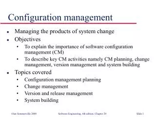
CM Fundamentals • CM Equilibrium Objective of Configuration Management • MarginsUsing CM to protect Design and Operating Margins • CM Process Model Restoring CM Equilibrium • Functional AreasFive Functional Areas of CM
What is CM Equilibrium? In its simplest terms Configuration Management is what we do to assure ourselves and our regulators that we are doing everything we said we would do. The objective of Configuration Managementis the conformance of the three elements represented by the CM Equilibrium Model
CM Equilibrium DesignRequire-ments Design Requirementstechnical requirements, derived from the design process, that are reflected in the final design. What Needs to be there • Design characteristics and bounding parameters needed for the design to work • Must be verified or monitored to confirm that design is valid
CM Equilibrium Facility Configuration Information (FCI) documentation that defines how the plant is designed and how we operate it. What we say is there • Design Output Documents • Operational Configuration Documents • Other Operating, Maintenance, Training and Procurement Information FacilityConfigInfo
CM Equilibrium Physical Configuration actual physical location, arrangement and material condition of SSCs What is actually there • SSCs installed (design configuration) • component position (operating configuration) Physical Config
CM Equilibrium DesignRequire-ments Work Processes must assure that: • Elements conform all the timeprocesses in place to restore CM Equilibrium if it is lost • All Changes are Authorizedpeople are trained and qualified • Conformance can be verifieddetermine what configuration is and prove it was done correctly PhysicalConfig FacilityConfigInfo
CM Equilibrium Upsets Design Require-ments Upsets Between Design Requirements & Facility Configuration Information • errors in analysis, design inputs • errors in licensing documents • Operating procedure invalidates design calculation (response time) • desired changes, such as power uprating FacilityConfigInfo
CM Equilibrium Upsets Upsets Between Physical Configuration & Facility Configuration Information • drawing / plant discrepancies • components in wrong position • maintenance errors that affect plant configuration • desired changes: modifications, manipulating plant components Physical Config FacilityConfigInfo
CM Equilibrium Upsets Design Require-ments Upsets Between Physical Configuration and Design Requirements • failure of SSC to meet performance criteria as designed • equipment out of tolerance • unexpected degradation in performance of SSCs Physical Config
CM EquilibriumMargins NSD 106.7 Figure 106-3 Design Basis Protect the Design Basis • Design Configuration conforms toDesign Basis • Operational Configuration conforms to Design Configuration Design Configuration Operational Configuration Each boundary has margins to protect these limits
INPO Margin Model Let’s view this cross-section Equipment /Function Failure Analyzed Design Limit Unanalyzed Margin Operating Limit Design Margin OperatingMargin Normal Operations Range of Normal Operation Operating Margin
Margins Failure Point Undetermineddepends on many variables Documented in engineering calculation Ultimate Capability Analytical Margin unanalyzed region Analyzed Design Limit Design Margin controlled by Engineering Operating Limit Operating Margin controlled by Operations Range of Normal Operation Documented on design documents
Margins Failure Point Undetermineddepends on many variables • Notes on Model • describes one parameter only; different parameters may be interrelated • direction may be positive or negative • doesn’t represent all possible limits and setpoints • gaps not intended to represent relative size of margins – may be zero Documented in engineering calculation Ultimate Capability Analytical Margin unanalyzed region Analyzed Design Limit Design Margin controlled by Engineering Operating Limit Operating Margin controlled by Operations Range of Normal Operation Documented on design documents
Margins Other Limits and Setpoints Failure Point Undetermineddepends on many variables Documented in engineering calculation Ultimate Capability Regulatory Limit Analytical Margin unanalyzed region Analyzed Design Limit Design Margin controlled by Engineering Operating Limit Operating Margin controlled by Operations Tech Spec Limit Range of Normal Operation Operator Alarm (HI-HI) Documented on design documents Operator Alarm (HI)
Elevator Example Margins Failure Point – undetermineddepends on many variables Ultimate Capability Analyzed & tested to 4650 lbs Analytical Margin Analyzed Design Limit Design Margin Dept of Labor - design for 25% passenger overload 4375 lbs Operating Limit Operating Margin Range of Normal Operation Rated Load posted in elevator = 3500 lbs 100 – 600 lbs
HVAC Example Margins • Original analysis: • Room temperature must be kept under 90° F to protect computers Note: vendor’s Operating Limit = utility’s Ultimate Capability • Analyzed Design Limit = 84° F, calculated for worst case conditions • Operating Limit =78° F to give operators time to take action (analysis assumption) • High Alarm is set at 75° F (warning of abnormal condition) 90° F Analytical Margin 84° F Design Margin 78° F Operating Margin • 75° F 72° F Normal Operation OAC Room Temperature
HVAC Example Margins • Over time margin is lost due to one or more of these causes: • heat loads added to room • lake temperature higher than analyzed • poor heat exchanger performance due to fouling 90° F Analytical Margin 88° F Design Margin • New Analyzed Design Limit (88°F) reduces Analytical Margin and • affects Operating Limit (78° F to 82°F) • affects Operating Margin • affects Alarm Setpoint (75° F to 78°F) 82° F Operating Margin • 78° F 74° F Normal Operation OAC Room Temperature
Analytical Margin Analytical Margin Design Margin Design Margin Operating Margin Operating Margin Normal Operation Normal Operation Voltage Analysis Roof Structural Analysis HVAC Example Margins • Larger air conditioning unit can restore room temperature margin but will • require more electrical power • increase weight on Aux Bldg roof 90° F Analytical Margin 84° F Design Margin 78° F Operating Margin • 75° F 72° F Normal Operation OAC Room Temperature …resulting in other margin losses
CM Process Model • high level model • integrated processes used to return CM Equilibrium • developed in early 2002 by CMBG task force. • included in INPO Ap-929, Revision 1 in 2005
CM Process Model ChangeDesignRequirements? ChangePhysicalConfiguration? ChangeFacilityConfigurationInformation? EvaluateIdentifiedProblem orDesiredChange DoNothing More No No No Evaluate Identified Problem or Desired Change • apparent discrepancy (discovered error) • desired change (modification, manipulating plant components) CM Equilibrium Yes Yes Yes CM001 DesignRequirementsChange Process Physical ConfigurationChangeAuthorizationProcess Facility ConfigurationInformationChange Process
CM Process Model ChangeDesignRequirements? ChangePhysicalConfiguration? ChangeFacilityConfigurationInformation? EvaluateIdentifiedProblem orDesiredChange DoNothing More No No No Change Design Requirements? • What are Design Requirements? • Does change affect Design Requirements? • Use Design Requirements change process CM Equilibrium Yes Yes Yes DesignRequirementsChange Process Physical ConfigurationChangeAuthorizationProcess Facility ConfigurationInformationChange Process CM002
CM Process Model ChangeDesignRequirements? ChangePhysicalConfiguration? ChangeFacilityConfigurationInformation? EvaluateIdentifiedProblem orDesiredChange DoNothing More No No No Change Physical Configuration? • Modify components or change position of components? • Use mod process to change design Configuration • Use operating procedures to change component position CM Equilibrium Yes Yes Yes DesignRequirementsChange Process Physical ConfigurationChangeAuthorizationProcess Facility ConfigurationInformationChange Process CM003
CM Process Model ChangeDesignRequirements? ChangePhysicalConfiguration? ChangeFacilityConfigurationInformation? EvaluateIdentifiedProblem orDesiredChange DoNothing More No No No Change Facility Configuration Information? • Design Output documents (drawings & specs) • Operational Configuration Documents • Other operating, maintenance, training, etc. CM Equilibrium Yes Yes Yes DesignRequirementsChange Process Physical ConfigurationChangeAuthorizationProcess Facility ConfigurationInformationChange Process CM004
CM Process Model ChangeDesignRequirements? ChangePhysicalConfiguration? ChangeFacilityConfigurationInformation? EvaluateIdentifiedProblem orDesiredChange DoNothing More No No No Do Nothing More • If cost effective, do nothing more…except • Document your conclusion CM Equilibrium Yes Yes Yes DesignRequirementsChange Process Physical ConfigurationChangeAuthorizationProcess Facility ConfigurationInformationChange Process
Functional Areas of CM #1 Protect the Design Basis Design Basis Configuration #2 Modify the Plant Engineering Change Control #3 Operate the Plant Operational Configuration Control #4 Maintain the Plant Configuration of SSCs not in service #5 Test the Plant Plant Design Validation
Functional Areas of CM Protect the Design Basis Objective: Understand and maintain design basis consistent with licensing basis design Major processes • control of licensing and design basis documents (such as 50.59 & UFSAR) • engineering calculations Causes for upsets in CM Equilibrium • new or revised Design Requirements • inadequate original review
Functional Areas of CM Modify the Plant Objective: Assure that changes to design configuration conform to Design Requirements and are accurately reflected on Facility Configuration Information Major processes • modification process Causes for upsets in CM Equilibrium • desired change (modification) • undocumented plant changes
Functional Areas of CM Operate the Plant Objective: Assure that alignment of in-service equipment is consistent with approved design through use of approved technical procedures. Major processes • operating procedures • tag out process Causes for upsets in CM Equilibrium • failure to follow operating procedures • human errors due to workarounds, abandoned equipment, temp mods, etc.
Functional Areas of CM Maintain the Plant Objective: Assure that SSCs are procured and maintained in accordance with approved design Major processes • maintenance procedures • procurement procedures Causes for upsets in CM Equilibrium • failure to follow procedures • inadequate procurement QA
Functional Areas of CM Test the Plant Objective: Assure the performance of SSCs meets Design Requirements Major processes • performance testing • plant walkdowns Causes for upsets in CM Equilibrium • inadequate performance testing programs • inadequate plant aging programs
“It’s what you do now When you don’t have to do anything That lets you be What you want to be When it’s too late to do anything about it.” Warren Owen, former Exec. VP Duke Power