Download

1 / 24
300 likes | 699 Views
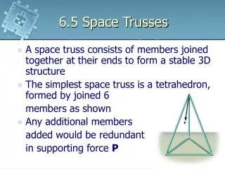
WORKSHEET 6 TRUSSES. Q1. When would we use a truss?. (a) long spans, loads not too heavy . (b) when want to save weight . (c) when have plenty of depth . (d) when want light appearance . 2/24. Q2. When would we not use a truss?. (a) don’t have the depth . (b) very large loads .

E N D
Q1 When would we use a truss? (a) long spans, loads not too heavy (b) when want to save weight (c) when have plenty of depth (d) when want light appearance 2/24
Q2 When would we not use a truss? (a) don’t have the depth (b) very large loads (c) don’t want fussy appearance (d) can’t provide lateral support if needed 3/24
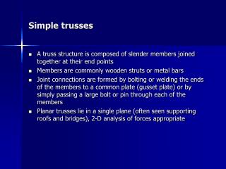
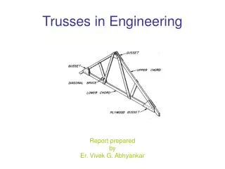
Q3 What are the main characteristics of trusses? (a) assembly of (short) linear members (b) members connected to form triangles (c) joints pinned (d) loads applied at panel points (joints) (d) members carry only tension or compression forces 4/24
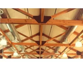
Q4 What materials are trusses most commonly made of? (a) steel (b) timber (c) concrete (very occasionally) 5/24
Q5 How are the joints commonly made? (a) in timber trusses (i) using gangnail joints - light timber (ii) using gusset plates (iii) overlapping/double members and bolts (iv) concealed plates - bolts (b) in steel trusses (i) gusset plates (ii) welded joints 6/24
Q6 What do the following do? (a) the chords (i) chords resist the bending moment (ii) top chords take the compressive forces (in a triangular truss, the top chord also resists shear) (iii) bottom chords take the tensile forces (b) the web members (i) resist the shear forces 7/24
Q7 What are the common span-to-depth ratios for: (a) timber beams? 18-20:1 (b) trusses? 5-10:1 8/24
(a) (c) (c) (b) Q8 In the truss below show where: (a) the maximumcompressive forcein a chord occurs (b) the maximum tensile force in a chord occurs (c) the maximumshear forcein a web member occurs 9/24
(c) (a) (b) Q9 In the truss below show where: (a) the maximumcompressive forcein a chord occurs (b) the maximum tensile force in a chord occurs (c) the maximumshear forcein a web member occurs 10/24
(a) given the force shown, what is H 45o (i) the horizontal component? V 10kN (ii) the vertical component? Q10 (a) H = 10 cos 45 = 7.07 kN to the right V = 10 sin 45 = 7.07 kN down 11/24
(b) given the force shown, what is H V 6kN (i) the horizontal component? 30o (ii) the vertical component? Q10 (b) H = 6 cos 30 = 5.2 kN to the right V = 6 sin 30 = 3.0 kN up 12/24
(c) given the two forces shown, use the parallelogram of forces or the triangle of forcesto find the resultant force 6kN 6kN 6kN 8kN R R Øo Øo 8kN 8kN Q10 (c) R = (62 + 82) Tan Ø = 6 / 8 = 0.75 = 10 kN at 36.87o Ø = 36.87o 13/24
4 bays @ 3m 3m 2kN 2kN 2kN 1kN 1kN B C E R2=4kN R1=4kN 45o A D F Q11 Analyze the truss shown below using the Methods of Joints First find the reactions. Using symmetry R1 = R2 = 8/2 = 4kN Assume all forces are in tension - i.e. away from the joint 14/24
AB A AD 4 1 B BC BD BA 4 DB (4.24) DC DA (0) DF D Q11 (cont1.) start at joint A (support) vertically: 4 + AB = 0 AB = -4.0 (compression) horizontally: AD = 0 next at joint B. vertically: 1 - 4 + BDsin45o = 0 BD = +4.24 (tension) horizontally:BC +4.24cos45o = 0 BC = -3.0 (compression) next at joint D. vertically: 4.24sin45o + DC = 0 DC = -3.0 (compression) horizontally: 0 +DF -4.24cos45o = 0 DF = +3.0 (tension) 15/24
2kN C CB 3 CE CF CD 3 2kN E EC 4 EG 4 EF Q11(cont2.) next at joint C vertically: 2 - 3 + CFsin45o = 0 CF = +1.41 (tension) horizontally: 3 +CE +1.41cos45o = 0 CE = -4.0 (compression) next at joint E. vertically: 2+ EF = 0 EF = -2.0 (compression) That completes half the truss. The other half is the same by symmetry 16/24
2kN 2kN 2kN 1kN 1kN B C E 3 3 0 3 3 3 0 3 2 4 4 4 4 4.24 4.24 1.41 1.41 A D F Q11 (cont3.) Note that thebiggestchord forcesare near themiddle and thebiggest web forcesare near theends Always true forparallel chord trusses withfairly uniform loading 17/24
4 bays @ 3m 3m 2kN 2kN 2kN 1kN 1kN B C E R2=4kN R1=4kN 45o A D F Q12 For the same truss use the Methods of Sections to find the forces in members BD, CE and DF First find the reactions. Using symmetry R1 = R2 = 8/2 = 4kN Assume all forces are in tension - i.e. away from the joint 18/24
1kN B C A D 4 Q12(cont1.) Make a cut through the truss passing through the member wanted, BD Consider the left part of the cut as a freebody Mark all the forces on it - including those members cut off the freebody is in equilibrium Using V = 0 4 - 1 -BD sin45o = 0 BD = 4.24 (tension) 19/24
2kN 1kN B C E 3m A D F 4 3m 3m Q12(cont2.) Make another cut through the truss passing through the other members wanted, CE and DF Mark all the forces on it - including those members cut off the freebody is in equilibrium Using M = 0 about F - consider all the forces on the left 4 x 6 - 1x 6 - 2 x 3 +CE x 3 = 0 CE = -4.0 (compression) Using M = 0 about C 4 x 3 - 1x 3 - DF x 3 = 0 DF = +3.0 (tension) Note that we have found only the members we wanted 20/24
4 bays @ 3m 2kN 2kN 2kN 1kN 1kN 3m 45o R2=4kN R1=4kN Q13 For the same truss use the Graphical Method to construct a Maxwell diagram and find the forces in the members First find the reactions. Using symmetry R1 = R2 = 8/2 = 4kN 21/24
4 bays @ 3m 2kN 2kN 2kN 1kN 1kN b c d e i k l n a f 3m h j m 0 g R2=4kN R1=4kN Q13(cont1.) First annotate using Bow’s Notation (label spaces between members and forces) First find the reactions. Using symmetry R1 = R2 = 8/2 = 4kN 22/24
a 4 i b 3 j 2 k c 1 m 0 o g scale for forces d l e n f Q13(cont2.) Next select a scale and draw a line representing all the loads and reactions all the loads are vertical - so is the line the line is the line a,b,c,d,e,f (ag, gf) ab = 1, bc = 2,...etc ag = 4, gf = 4 begin with a zone near a reaction, e.g h ah is vertical and gh is horizontal - meet at g (h & g at same point) hg is 0 h take next zone - i bi is horizontal and ih is at 45o - draw these lines they meet at i Now ijis vertical and jg is horizontal. This locates j Proceed to k in same way and half the truss is solved Measure all lines - this gives the force in each member need to use a special convention to determine tension or compression 23/24
Q14 When would you use: (a) the Method of joints? When want to do detailed design and need to know all the forces in all members (b) the Method of Sections? When want to know only a few member forces e.g. end diagonals and middle chords (b) the Graphical Method When don’t have a calculator or don’t want to calculate 24/24