Download
1 / 46
460 likes | 546 Views
Environmental Testing, Design, Analysis for HABs. By: Ara Kourchians (arko). About Me. Undergrad at Cal Poly Pomona Electrical Engineering – emphasis in control systems Work for JPL/NASA Software engineer for electronic part reliability testing/reporting systems Previous projects and work

E N D
Environmental Testing, Design, Analysis for HABs By: Ara Kourchians (arko)
About Me • Undergrad at Cal Poly Pomona • Electrical Engineering – emphasis in control systems • Work for JPL/NASA • Software engineer for electronic part reliability testing/reporting systems • Previous projects and work • Omni-directional drive system robots • Self-balancing robots • Time machines • Harsh environment sensors • Plasma Lighting RF Ballasts • Many self-funded projects • DISCLAMER I am NOT here to represent JPL/NASA, all opinions are my own. Information provided is publically available information (google it yo).
Assumptions • You already know what a HAB is • Basic understanding of electronics and physics • Goal: Increase the reliability of your HAB
Failure • Software • Power/Radio Hardware configuration • Environment
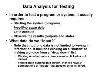
TESTING TESTING TESTING Input Code Output Verify • Software • Test Harness • Full flight systems test without debugger, power supply, etc • “Pretend you are going to launch it” • Power/Radio Hardware configuration • Know your datasheets • Full battery test • Range test & dry run • EMC • Environment • Cold, Vacuum, IR, Shake
Software Testing GPS Code Input Output Verify • Unit Testing • Make up data • neg/poslat/long • Test cases • Bad NMEA packet • GPS signal loss • Reset Procedure • Proper FSM • Integration/System Testing • Static Testing • Peer review • Static Code Analysis • KNOW YOUR EMBEDDED HARDWARE AND COMPILER Radio Code Input Output Verify System Code Input Output Verify GPS Code Radio Code System Code Input Output Verify
Software Standards • What does JPL do? (YES THIS IS PUBLIC INFO) • People hate following rules and want to follow their own • Pick 10 standard/rules and make them easy to remember • Each tied to a real failure • Power of 10 Rules for developing safety-critical code (C language) • No spaghetti code flow (goto, recursion, etc) • All loops must have fixed bounds (stops runway code) • Avoid heap memory allocation (avoid malloc() ) • Keep function line count short (less than ~60 lines) • At least two runtime assertions per function (verify conditions pre/post func) • Keep data objects at smallest possible level of scope • Check functions return value or cast as void, check function input parameters • Use precompiler for headers and simple macro definitions • Limit pointer use to a single dereference, no function pointers • Warnings are errors, must compile with no warnings (set compiler to most pedantic) • Lock down code, any changes means going back and testing all over again http://web.eecs.umich.edu/~imarkov/10rules.pdf http://lars-lab.jpl.nasa.gov/JPL_Coding_Standard_C.pdf
Power/Radio hardware testing • Know your datasheets, estimate power draw • Good connectors • Power supply test operating voltage range (Vmin to Vmax) • Estimate battery life • Full battery test • Range Test A good distance
EMC & Derating • Derating (not really necessary for HAB’s) • Run electronics below maximum rating to increase lifetime/reliability • Under clock CPU to prevent overheating • Prevent accidental damage • EMC • Capacitive, Inductive, Radiative, Conductive • Could be as simple as running all your radios close to each other • Power Amplifier degradation • General interference (especially RX) • Transmit your ham gear near it to test robustness • Commercial equipment is usually rated • Homebrew PCB’s are not rated http://www.williamson-labs.com/ltoc/glencoe-emc-11.htm
RUN EMC I.E. – Radiated Field Strength (dBuV/m) Susceptibility 50 40 30 Emission 20 10 1 10 100 1000 10000 Frequency (MHz)
EMC • Radiated (30MHz – 10GHz) • Emission: Clock & data lines, switching power supplies, poor RF config • Susceptibility: Clock & data lines in bad places, bad termination • Solution: Balance transmission lines, ground planes, shielding, correct termination, filters, differential lines • Conducted (100kHz – 30MHz) • Emission: Switching power supplies, motors, switches, relays • Susceptibility: Noisy AC power, Poor decoupling on power • Solution: Decoupling, power filters, shielding, ground planes http://www.williamson-labs.com/ltoc/glencoe-emc-11.htm
Environmental Road Map • Understand the environment • Design/Understand your hardware • Determine tests • Build test rig • Test • Analyze • Redesign
Environment • What are the expected environmental conditions of nearspace? • Air Temperature: -60C to +40C • Pressure: 0.01atm (1010Pa) to 1atm (101325Pa) • Winds: 0mph – 100mph • Forces: up to 10g • Humidity: 0% - 100% • Solar Heat (Irradiance): 180 W/m^2 - 340 W/m^2 • Radiation: <0.1krad/year (to put into perspective: HAB experiences 1 CT scan for each day of flight)
Environment • What are the expected environmental conditions of nearspace? • Air Temperature: -60C to +40C • Pressure: 0.01atm (1010Pa) to 1atm (101325Pa) • Winds: 0mph – 100mph • Forces: up to 10g • Humidity: 0% - 100% • Solar Heat (Irradiance): 180 W/m^2 - 340 W/m^2 • Radiation: <0.1krad/year (to put into perspective: HAB experiences 1 CT scan for each day of flight) Your HAB would need to fly for 10 years at 30km for radiation to become a legitimate concern
Environment IR Sky Solar Flux Convection Albedo Cloud Radiation Albedo Ground IR Ground
Environment IR Sky Solar Flux Convection drops off after 18,000m Convection Albedo Cloud Radiation Albedo Ground IR Ground
Environment Babbage, 2013 43rd International Conference on Environmental SystemsThermal Design and Analysis of the Supersonic Flight Dynamics Test Vehicle for the Low Density Supersonic Decelerator Project (doi: 10.2514/6.2013-3348) http://arc.aiaa.org/doi/abs/10.2514/6.2013-3348
Understand your hardware • Datasheets • Operating Temperature • Heat generated (depends on parts) • Your HAB falls in two categories • Hot HAB – Overheats & fails at altitude • Power regulator, powerful processor, etc • Cold HAB - Freezes & fails at altitude • Low power parts
What are you testing? • Can your HAB survive the expected temperatures? • Electronic parts (-40C – +80C) • How well does your insulation work? • Does your HAB overheat? (Do your parts need cooling?) • Camera • Power Regulator • Cutdown • “New Tech” or “mystery box” • Anything that acts significantly different in a vacuum
Spacecraft Thermal Modeling • Model & Simulate • “Everything on” (Hottest Case) • “Bare minimum” (Coldest Case) http://www.esmats.eu/amspapers/pastpapers/pdfs/2012/johnson.pdf
How do you know if you’re a hot or cold HAB? • Just test it! • Room temperature / Ice test • Cheap ($10) • Test parts to rating • Answers questions like: • does temp increase at room temp? • How do the characteristics change at cold? • Build Thermal/Vacuum/IR chamber • Expensive ($100-200) • Good test & data
Environmental Chamber(on a budget $100-$200) • Air Temperature -60C to +40C: Dry Ice, Hair Dryer • Pressure 0.01atm to 1atm: Refrigerator Pump • Solar heat 184 W/m^2 - 341 W/m^2 : Light Bulb, Heat lamp • Winds/Forces up to 10g: Stairs (Ed Method) • Humidity 0% - 100%: Spray Bottle
ENV Chamber Design - Vacuum 12.7mm polycarbonate glass Silicone Rubber Vacuum Pump Schedule 40 PVC Tee
ENV Chamber Design - Cold Heat sink Peltier Cooler Heat Transfer Rod Dry Ice
ENV Chamber Design – Solar Heat Light Bulb
Vacuum of nearspace Setup Deep space or ground Sun HAB
Dry Ice Vacuum of nearspace Setup Deep space or ground Sun HAB
Poor Results DEEP SPACE SIDE SUN SIDE Cooling Rod Altitude
Vacuum of nearspace Setup Deep space or ground Fishing Line Sun Dry Ice Cloth HAB Note: Vacuum pump must run continuously
Good Results SUN SIDE DEEP SPACE SIDE Chamber Wall Temperature Altitude
Results - Sun Side - Internal - Deep Space Side
Design Improvements • Thermal shroud with Liquid Nitrogen, cold isopropyl, or glycol pumped through the walls • Proper coating for maximum thermal absorptivity • Control System • Lazy Susan
Now you know… But how do you solve these thermal problems?
Solving the thermal problems • Hot HAB • Radiator – Copper braid & white acrylic paint (high emissivity) • Aluminum foil or heat blanket (low absorptivity) • Software (turn things off when not in use, underclock, etc) • Single/Multiple component heating is solved with radiators • Place radiators on sides or bottom Radiator Hot HAB Earth State Deep Space or Ground http://ukhas.org.uk/guides:materials http://www.engineeringtoolbox.com/emissivity-coefficients-d_447.html http://www.engineeringtoolbox.com/radiation-surface-absorptivitie-d_1805.html
Solving the thermal problems • Cold HAB • Insulate - Foamular or Styrofoam (extruded polystyrene) • Black body - Acrylic craft paint (high absorptivity) • Heater (wastes power, should have a control system to prevent becoming Warm HAB) Heater Cold HAB Earth State Insulate http://ukhas.org.uk/guides:materials http://www.engineeringtoolbox.com/emissivity-coefficients-d_447.html http://www.engineeringtoolbox.com/radiation-surface-absorptivitie-d_1805.html
Solving the thermal problems • MLI (Multi Layer Insulation) • Aluminum or Silver • Mylar • Kapton • Polyester mesh • R-value of >>5 K*m^2/W • Foamular • R-value of 0.88 K*m^2/W http://ukhas.org.uk/guides:materials
What is Conformal Coating? • Non conductive dielectric layer for protecting PCB’s Why Conformal Coating? • Thermal stability and evenness • Conductive heat transfer • Corrosion prevention • Humidity • Accidental shorting • Whiskering Courtesy of DanielSaul NOTE: Thermal expansion could damage parts
Conformal Coating • Acrylic • Low cost, durable, water resistant, fast dry • Silicone • Temperature resistant, flexible, water resistant, great insulator • Urethane • Chemical/Corrosion protection, thermal shock, moisture resistant • Application: Avoid bubbles, don't go too thick or too thin • Recommended Suppliers: MG Chemicals, Techspray http://www.humiseal.com/product-selector/conformal-coating
Thanks! • Questions? • Email: arko2600@gmail.com • arkorobotics.com/env