Download
1 / 24
240 likes | 346 Views
Quiz 1. a) Find the currents i 1 and i 2 in the circuit in the figure. b) Find the voltage v o . c) Verify that the total power developed equals the total power dissipated. Quiz 2. The current i a in the circuit shown in the figure is 2 mA . Find i o i g

E N D
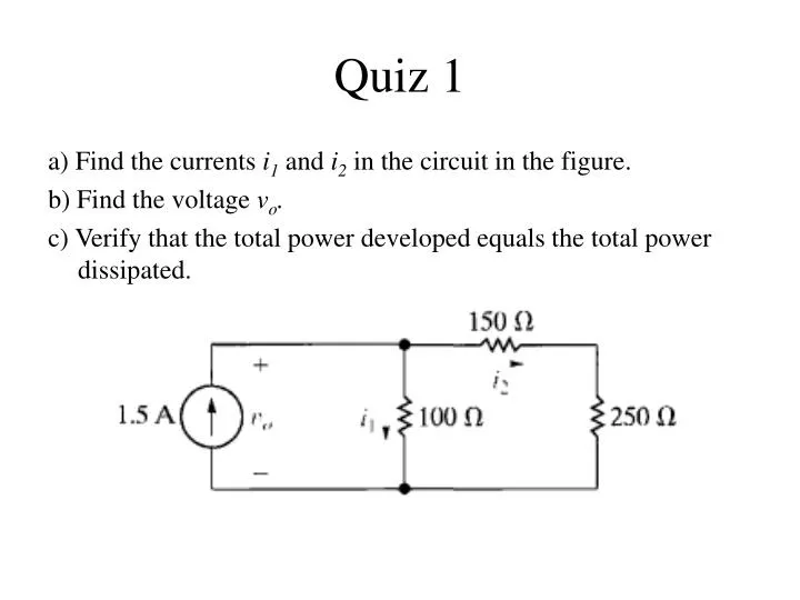
Quiz 1 a) Find the currents i1 and i2in the circuit in the figure. b) Find the voltage vo. c) Verify that the total power developed equals the total power dissipated.
Quiz 2 The current ia in the circuit shown in the figure is 2 mA. Find • io • ig • Verify that the total power developed equals the total power dissipated.
Outline • Resistors in series • Resistors in parallel • The voltage divider and the current divider circuits • Voltage division and current division • Measuring voltage and current • The ∆-to-Y transformation.
Resistors in series • Series-connected circuit elements carry the same current. • Series resistors can be combined to obtain a single equivalent resistance according to the equation: • Note that the resistance of the equivalent resistor is always larger than that of the largest resistor in the series connection.
Resistors in parallel • Parallel-connected circuit elements have the same voltage across their terminals. • Parallel resistors can be combined to obtain a single equivalent resistance according to the equation: • Note that the resistance of the equivalent resistor is always smaller than the resistance of the smallest resistor in the parallel connection.
Two resistors in parallel • When just two resistors are in parallel, the equation for equivalent resistance can be simplified to give:
Example 1 Find is, i1, and i2 in the circuit shown in the figure. ----------------------------------- and
The voltage divider circuit • When voltage is divided between series resistors the voltage across each resistor can be found according to the equations: • These equations show that v1 and v2 are fractions of vs. • Each fraction is the ratio of the resistance across which the divided voltage is defined to the sum of the two resistances. • Because this ratio is always less than 1, the divided voltages v1 and v2 are always less than the source voltage vs.
Example 2 The resistors used in the voltage-divider circuit shown in the figure have a tolerance of ±10%. Find the maximum and minimum value of vo? ----------------------------- The maximum value of vo occurs when R2 is 10% high and R1 is 10% low, and the minimum value of vo occurs when R2 is 10% low and R1 is 10% high.
The current divider circuit • When current is divided between parallel resistor the current through each resistor can be found according to the equations: • These equations show that the current divides between two resistors in parallel such that the current in one resistor equals the current entering the parallel pair multiplied by the other resistance and divided by the sum of the resistors.
Example 3 Find the power dissipated in the 6 Ω resistor shown in the figure. ----------------------------------------------- First, we must find the current in the resistor by simplifying the circuit with series-parallel reductions. Then, we find the current iobyusing the formula for current division: and the current in the 6 Ω resistor is: and the power dissipated in the 6 Ω resistor is: p = (3.2)2(6) = 61.44W.
Voltage division • The voltage drop vj across a single resistor Rj from a collection of series-connected resistors is proportional to the total voltage drop v across the set of series connected resistors. • The constant of proportionality is the ratio of the single resistance to the equivalent resistance of the series connected set of resistors, or Rj/Req.
Current division • The current ij through a single resistor Rjfrom a collection of parallel-connected resistors is proportional to the total current i supplied to the set of parallel connected resistors. • The constant of proportionality is the ratio of the equivalent resistance of the parallel-connected set of resistors to the single resistance, or Req/Rj. • The constant of proportionality in the current division equation is the inverse of the constant of proportionality in the voltage division equation.
Example 4 Use current division to find the current io and use voltage division to find the voltage vo for the circuit in the figure. ---------------------------- we can find the equivalent resistance of the four parallel branches containing resistors: and ioand v: and vo
Measuring voltage & current • A voltmeter is an instrument designed to measure voltage; it is placed in parallel with the element whose voltage is being measured. • An ideal voltmeter has infinite internal resistance and thus does not alter the voltage being measured. • An ammeter is an instrument designed to measure current; it is placed in series with the circuit element whose current is being measured. • An ideal ammeter has zero internal resistance and thus does not alter the current being measured.
Digital vs. analog meters • An ideal ammeter or voltmeter has no effect on the circuit variable it is designed to measure. • Digital meters and analog meters have internal resistance, which influences the value of the circuit variable being measured. • Digital meters offer several advantages over analog meters: • They introduce less resistance into the circuit to which they are connected, • They are easier to connect, • The precision of the measurement is greater due to the nature of the readout mechanism.
The ∆-to-Y transformation Ra Rb R3 R2 R1 Rc
The Y-to-∆ transformation Ra Rb R3 R2 R1 Rc
Example 5 Find the current and power supplied by the 40 V source in the circuit shown in the figure. ------------------------------- By replacing the upper ∆. We then compute the three Y resistances as:
Example 5 the equivalent resistance is and the current in the circuit is: i= v/R = 40/ 80= 0.5A and the power is : p= v*i= 40*0.5 = 20W
Summary • Series resistors can be combined to obtain a single equivalent resistance according to the equation: • Parallel resistors can be combined to obtain a single equivalent resistance according to the equation: • When just two resistors are in parallel, the equation for equivalent resistance can be simplified to give:
Summary • When voltage is divided between series resistors the voltage across each resistor can be found according to the equations: • When current is divided between parallel resistor the current through each resistor can be found according to the equations: • Voltage division is a circuit analysis tool that is used to find the voltage drop across a single resistance from a collection of series-connected resistances when the voltage drop across the collection is known:
Summary • Current division is a circuit analysis tool that is used to find the current through a single resistance from a collection of parallel-connected resistances when the current into the collection is known: • A voltmeter measures voltage and must be placed in parallel with the voltage being measured. • An ammeter measures current and must be placed inseries with the current being measured. • A circuit with three resistors connected in a ∆ configuration can be transformed into an equivalent circuit in which the three resistors are Y connected.