Download
1 / 15
180 likes | 547 Views
Design of Supersonic Intake / Nozzle. P M V Subbarao Associate Professor Mechanical Engineering Department I I T Delhi. Meeting the Cruising Conditions…. Design Analysis. For a known value of Mach number, it is easy to calculate area ratio.

E N D
Design of Supersonic Intake / Nozzle P M V Subbarao Associate Professor Mechanical Engineering Department I I T Delhi Meeting the Cruising Conditions…
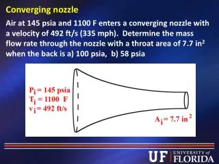
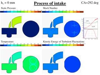
Design Analysis For a known value of Mach number, it is easy to calculate area ratio. Throat area sizing is the first step in the design. If we know the details of the resource/requirements, we can calculate the size of throat.
Cryogenic Rocket Engines A ratio of LO2:LH2 =6:1 T0 = 3300K. P0 = 20.4 Mpa
Specifications of A Rocket Engine • Specific Impulse is a commonly used measure of performance For Rocket Engines,and for steady state-engine operation is defined As: • At 100% Throttle a RE has the Following performance characteristics Fvacuum = 2298 kNt Ispvacuum = 450 sec.
Design Procedure Select a technology : Isp & Fthrust Estimate the mass flow rate of propellent. Carryout heat release or combustion calculations and estimate T0 & p0
Compute properties of gas at each location. Terminate the design when local static pressure is almost zero. This is exit of the nozzle. Compute Maximum Mach number at the exit. This Mach number will generate the required thrust.
• Temperature T0 = 3300K Tthroat = 2933.3 K
• Pressure P0 = 20.4Mpa Pthroat = 11.32 MPa
Any Doubts !!! The maximum number corresponding to an almost zero static pressure of the gas. This design is meant to work only in Vacuum !!! What is its performance while launching ??? What is the thrust at sea level ? Will the nozzle exit flow be a supersonic ?
SEA Level Performance What happens if it is not possible to obtain the design mass flow rate ? One needs to know the Mach number distribution for a given geometric design! Ambient Pressure is maximum at Sea level. The design conditions are vacuum. Will the mass flow rate be same ? How to Calculate the corresponding Mass flow rate of propellant ? Will p0 and T0 remain same ?
Find the Maximum Mach number at sea level Calculate mass flow rate possible at sea level. Will it satisfy the throat condition?