1 / 2
40 likes | 134 Views
We are providing online solutions and services for image processing in India. Buy our products of comprehensive machine vision software and image processing software for a point and click environment to develop, test, and install applications.<br>

E N D
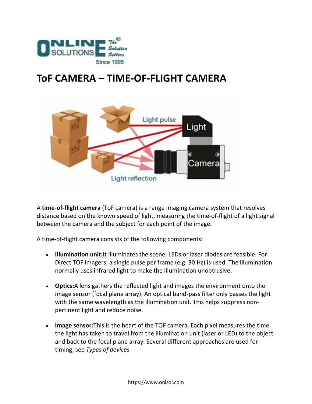
ToF CAMERA – TIME-OF-FLIGHT CAMERA A time-of-flight camera (ToF camera) is a range imaging camera system that resolves distance based on the known speed of light, measuring the time-of-flight of a light signal between the camera and the subject for each point of the image. A time-of-flight camera consists of the following components: Illumination unit:It illuminates the scene. LEDs or laser diodes are feasible. For Direct TOF imagers, a single pulse per frame (e.g. 30 Hz) is used. The illumination normally uses infrared light to make the illumination unobtrusive. Optics:A lens gathers the reflected light and images the environment onto the image sensor (focal plane array). An optical band-pass filter only passes the light with the same wavelength as the illumination unit. This helps suppress non- pertinent light and reduce noise. Image sensor:This is the heart of the TOF camera. Each pixel measures the time the light has taken to travel from the illumination unit (laser or LED) to the object and back to the focal plane array. Several different approaches are used for timing; see Types of devices https://www.onlsol.com
Driver electronics:Both the illumination unit and the image sensor have to be controlled by high speed signals and synchronized. These signals have to be very accurate to obtain a high resolution. For example, if the signals between the illumination unit and the sensor shift by only 10 picoseconds, the distance changes by 1.5 mm. For comparison: current CPUs reach frequencies of up to 3 GHz, corresponding to clock cycles of about 300 ps – the corresponding ‘resolution’ is only 45 mm. Computation/Interface:The distance is calculated directly in the camera. To obtain good performance, some calibration data is also used. The camera then provides a distance image over some interface like USB and Ethernet The simplest version of a time-of-flight camera uses light pulses or a single light pulse. The illumination is switched on for a very short time, the resulting light pulse illuminates the scene and is reflected by the objects in the field of view. The camera lens gathers the reflected light and images it onto the sensor or focal plane array. Depending upon the distance, the incoming light experiences a delay. Applications areas include Machine Vision (Measurement), Automative (safety), Robotics, Gaming, Human machine interfacing, Topography. For more information, contact: info@onlsol.com and for cameras in ToF check www.baslerweb.com Source : https://www.onlsol.com/blog/tof-camera/ https://www.onlsol.com