Download
1 / 17
170 likes | 561 Views
Power Factor Correction using Power Factor Transducer and Microcontroller. Submitted by debadatta patro (090101eer024) madhu sudan samantray bhuyan (090101eer041) g. Anil kumar (090101eer059) Anil kumar sahu (090101eer012) subhransu kumar sahu (090101eer001). project guide

E N D
Power Factor Correction using Power Factor Transducer and Microcontroller Submitted by debadattapatro (090101eer024) madhusudansamantraybhuyan (090101eer041) g. Anil kumar (090101eer059) Anil kumarsahu (090101eer012) subhransukumarsahu (090101eer001) project guide Asst. prof. suchitalakra
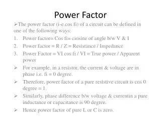
INTRODUCTION • Power factor (PF) is a measurement by which we can measure the efficiency of the electrical equipments as well as ac electric power system on the basis of electrical energy consumption. It determines power quality. • Due to inductive loads, the apparent power becomes greater than the real power that increases the phase difference between voltage and current. So, the power factor drops below unity and the system becomes less efficient. • Our project deals with correcting the power factor to make it closer to unity.
WHAT IS A POWER FACTOR • It Is a measure of how effectively the current is being converted into useful work output • It Is a good indicator of the effect of the load current on the efficiency of the supply system. • Power factor = cosѲ, where ‘Ѳ’ is the phase angle • power factor=P/S, where p=real power, s=apparent power.
Apparent power KVA KVAR Reactive power KW Real power
Cause of low power factor • Since power factor is defined as the ratio of KW to KVA, we see that low power factor results when KW is small in relation to KVA. • Inductive loads are responsible for high KVAR resulting a low power factor. KVA KVAR KVA KVAR KW KW • So , inductive loads (with large KVAR) result in low power factor.
What Is Power Factor Correction? A high power factor is generally desirable in a transmission system to reduce transmission losses . Generally power factor correction is for two type of loads :linear load, Non linear load. Power factor correction brings the power factor of an AC power circuit closer to 1 by supplying reactive power.
Overview of the System Incandescent bulbs Power line Power supply Current transformer Capacitor bank Switching drives Power factor transducer : LTPFU relay Microcontroller Atmega 32 LCD display (Block Diagram of the existing system) (Block Diagram of the proposed system)
Equipments required for hardware implementation • Power Factor Transducer • Power Factor Transducers measure the power Factor in 1 Phase and 3 Phase electrical systems. The resulting output signal is directly proportional to the system power factor. The output can be connected to Recorders for display, analysis or control. • In our project we are using a power factor transducer of model: LTPFU.
MICROCONTROLLER • Here we are using a atmega16 microcontroller
CAPACITOR BANK • When power factor improvement capacitor banks are designed and arranged properly, the PF correction scheme becomes efficient. The capacitor bank is comprised of individual capacitor elements. • salient features of PF correction capacitor banks are extremely high reliability with self-healing capabilities; capable of controlling the requirement of kVARs to achieve PF as close as unity; compact, efficient and long service life; protected against over-voltage, over-current, over temperature, switching surges.
PROGRESS LCD interfacing Program ADC Programming
Here soldering were done on 16*2 LCD for interface with microcontroller 16 pin of LCD were connected with AVR burner.Pin1-GND,Pin2-VCC,Pin3-GND,Pin4-PD0.4(5th pin PORT D), Pin5-PD0.5(6th pin PORT D), Pin6-PD0.6(7th pin PORT D), Pin7-PA0.0(1th pin PORT A), Pin8-PA0.1(2th pin PORT A),Pin9-PA0.2(3th pin PORT A), Pin10- PA0.3(4th pin PORT A), Pin11- PA0.4(5th pin PORT A),Pin12- PA0.5(6th pin PORT A), Pin13- PA0.6(7th pin PORT A), Pin14PA0.7(8th pin PORT A),Pin15-VCC- (9th pin PORT C), Pin16- GND-(10th pin PORT A) Connection were done as per the function of the LCD and microcontroller . Then we build the program in AVR-4 Software with no error and we got the output
REFERENCES http://cmrt.centrale-marseille.fr/cpi/ever09/documents/papers/ev7/EVER09-paper-142. http://blog.dianyuan.com/blog/u/51/1174286041.pdf http://www.mouser.com/ds/0/mikroElektronika/mikroc_pro_avr_manual_v100-16829.pdf http://www.atmel.com/Images/doc2503.pdf http://www.mouser.com/ds/0/mikroElektronika/mikroc_pro_avr_manual_v100-16829.pdf http://www.emt-ndia.net/equipment_tips/electrical_system/pdf/Diane%20Power%20Factor.pdf