Download
1 / 55
550 likes | 685 Views
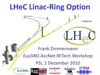
Ring- Linac LHeC. Frank Zimmermann, CERN, BE-ABP Contributors:

E N D
Ring-LinacLHeC Frank Zimmermann, CERN, BE-ABP Contributors: F. Bordry, H.-H. Braun, O.S. Brüning, H. Burkhardt, A. Eide, A. de Roeck, R. Garoby, B. Holzer, J.M. Jowett, T. Linnecar, K.-H. Mess, J. Osborne, L. Rinolfi, D. Schulte, R. Tomas, J. Tückmantel, A. Vivoli, CERN, Geneva, Switzerland; S.Chattopadhyay, J. Dainton, Cockcroft Inst., Warrington; M. Klein, U.Liverpool, United Kingdom; A.K. Ciftci, Ankara U.; H. Aksakal, U. Nigde, Turkey; S. Sultansoy, TOBB ETU, Ankara, Turkey; J. Skrabacz, U. Notre Dame, U.S.A.; T. Omori, J. Urakawa, KEK, Japan; F. Willeke, V. Litvinenko, V. Yakimenko, BNL, New York, U.S.A.; C. Adolphsen, SLAC, U.S.A. 2nd CERN-ECFA-NuPECC Workshop on the LHeC Divonne, 1 September 2009
particle-physics requests (John Dainton, Max Klein) • lepton energies from 50 to 150 GeV • peak luminosity ~1033 cm-2s-1 or higher • both e- and e+ beams • polarization
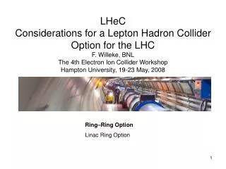
LHeC options including linacs option 1: “ring-ring” (RR) e-/e+ ring in LHC tunnel option 2: “ring-linac” (RL) s.c. linac up to 70 GeV:option for cw operation and recirculation with energy recovery; > 70 GeV: pulsed operation at higher gradient ; g-hadron option; focus on option 2 SPL, operating with leptons, as injector for the ring, possibly with recirculation;
2-pass Recirculating Linear Accelerator (RLA), 100-140 GeV– pulsed, high gradient LHC LHeC LINAC
4-pass Energy Recover Linac (ERL) 60 GeV– cw, lower gradient LHC LHeC LINAC
3-km long greenfield SC linac “ILC-like” SC linac parameters Anders Eide 4 passes 2 passes RF frequency: ~700 MHz we can use the same linac for all energies! (different klystrons and modulators for cw and pulsed mode)
can one build a 3-km long linac? it has been done before (some 50 years ago)
return arc and return drift • choice of arc radius = 1.5 km • dictated by synchrotron radiation • energy loss • - 140 GeV (70 GeV in arc): 2% energy loss • - 100 GeV (50 GeV in arc): 0.7% energy loss • - 60 GeV (30 GeV in arc): 0.1% energy loss • emittance growth (controlled by the arc-cell length) • return arc length = linac length • total RLA circumference: ~(2x3+2px1.5)km ~15 km
construction cost assumptions rough estimate for cost / (unit length) extracted from XFEL, ILC and ELFE designs [w/o escalation]: • linac: 160 k$/m (assuming 1$~1€) • -with eff. gradient of 11.8 MV/m (XFEL, 20GV, 1.7 km) • arc section: 50 k$/m • -300 M$ per ILC Damping Ring • drift straight: 10 k$/m • - vacuum + perhaps some diagnostics?, taken as ~20% of cost of arc section from ELFE design • ILC tunnel cost: ~5k $/m • - already taken to be included in above numbers • - otherwise important only for the straight drifts, potentially raising the drift cost to 15k$/m
optimized cost vs energy J. Skrabacz J. Skrabacz, “Optimizing Cost and Minimizing Energy Loss in the Recirculating Race- Track Design of the LHeC Electron Linac,” U.M., CERN REU, 2008; CERN-AB-Note-2008-043 adding weight parameter l in units of MEuro/(GeV energy loss) to limit operating cost “optimum of optimum” cost increases about linearly withenergy 2-pass acceleration is optimum from ~50-140 GeV
R-L construction cost estimate construction of 140-GeV RLA: ~1 billion € + IR, sources, escalation, LHC modifications → total cost ~1.5-2.0 billion €
RLA lattice • optics design using PLACET and MAD-X for three scenarios • 60 GeV 4-pass system with deceleration • 100 GeV 2 passes • 140 GeV 2 passes • considered injection energies of 5 GeV and 0.5 GeV (final choice) Anders Eide for ER option return drift arc 2 dispersion suppressor and matching sections arc 1 linac to IP from injector Linac (500 MeV)
master thesis Anders Eide Conclusion http://ab-abp-clic-qcde.web.cern.ch/ab-abp-clic-qcde/Literature/Project_Eide.pdf
RLA optics constraints same quadrupole magnets determine optics on several passes through the linac at different beam energies → stability constraints phase adv./cell at start of 2ndlinac pass depends on phase adv./cell in 1st pass & injection energy Anders Eide
linac phase advance phase adv/cell, 0.5-100 GeV RLA phase adv/cell, 0.5-60 GeV ERL 1st pass, 130o constant 2nd pass, 1o→54o 1st pass: 130o→2o 2nd pass 3rd pass 4th pass local maximum for subsequent passes results from combined change of beam energy and quadrupole gradient quadrupole gradient for 60 GeV ERL quadrupole gradient for 100 GeV RLA Anders Eide
basic cell & magnet parameters Anders Eide standard FODO cell everywhere cell length = 24 m (except 2nd & 5th transition of 60 GeV ERL [48 m]) quadrupole length 470 mm everywhere maximum quadrupole gradient 78 T/m (at end of 140 GeVlinac) separation between quadrupoles 11.53 m to accommodate rf cavities or dipoles, orbit correctors, BPMs, etc. dipole length 9.8 m rf-cavity length 8.4 m bending radius of dipoles in recirculating arc = 1.5 km 90o phase advance in the return arcs and return drift
linac injection energy • low energy encouraged by Georg Hoffstaetter • advantages of low (500 MeV) injection: • for 2-pass recirculatinglinac [100 or 140 GeV] • slightly reduced linac length ~2% w.r.t. 5 GeV • strong impact on energy recovery (ER) efficiency • hmax~(Ecoll-Einj-DESR)/Ecoll, luminosity~/(1-hmax) • disadvantage: • large beta functions at transitions & linac ends • loss of adiabaticity and significant beating
linac-arc transitions Anders Eide 1st of 2 transition in the 100 & 140 GeV RL, similar for all RL, 130o→90o 2nd of 2 transitions for the 140 GeV RL, 130o→0.7o 5th of 6 transitions for the 140 GeV RL, 1.9o→90o
complete optics – 2 passes 100 GeV RLA 140 GeV RLA 2nd pass 50.3→ 100 GeV 2nd pass 70.3→ 140 GeV 1st pass 0.5→ 50.3 GeV 1st pass 0.5→ 70.3 GeV return arcs & drift return arcs & drift Anders Eide
complete optics – 60 GeV ERL Anders Eide 2nd pass 30.3→ 60 GeV 3rd pass 60 → 30.3 GeV 4th pass 30.3 → 0.5 GeV 1st pass 0.5→ 30.3 GeV return return return
RLA & ERL optics performance • addressed in simulation studies • by Yi-Peng Sun (talk tomorrow) • MAD-X code modifications for RLAs • multi-particle tracking with energy spread • and synchrotron radiation • - emphasis on emittance
PLACET/MAD-X benchmarks good agreement between MAD-X and PLACET linacs Anders Eide 5 → 100 GeV βx,max= 458m βy,max= 154m Placet (linac only) MAD-X (with arcs) 5 → 60 → 13 GeV βx,max= 524m βy,max= 172m
electric power for cryogenics Eide: “Electrical Power of Ring- Linac Options for LHeC,’’ T4 Report, 2008 dynamic static heat load cryogenics electric power vs. acc. gradient: cw operation requires low gradient ~10 MV/m recirculation and 700 MHz frequency further lower cryo- power needs 70 GeV beam energy A. Eide, D. Schulte, T. Linnecar, J. Tückmantel EPAC’08
RF & total electric power A. Eide, H. Braun hwp→rf~ 50% for s.c. linacs hrf→beam~ 100% in cw mode hrf→beam~ Tb/(Tb+(Trf,ref-Tb,ref)Iref/I ) in pulsed mode hERL~ 90-98% with ERL option, 0 else total el. power cryo power rf power
two p beam scenarios * focusing one p beam in the following consider phase-II upgrade parameters; for phase-I parameters expect ~5 times lower luminosity (note that SPL and PS2 can deliver ~4x10¹¹p/bunch at 25 ns spacing)
IP parameters both beams are taken to be round; e- beam is assumed to be matched to p beam: sp*=se* luminosity: average e- beam current (limited by available el. power, linac technology & beam dynamics) H. Braun, C. Adolphsen, F. Z. proton brightness (limited by s.c. in injectors and LHC pp beam-beam) p b function limited by IR layout, chromatic correction, and also by the e- hourglass reduction factor
e-p hourglass factor & pb* limit x=be*/sz,p r=ee/ep Note: linacgeee~ 10-100 mm smallest LEP geee ~2 mm at 60 GeV b*p vs. geeefor two values of Hhgassuming E=60 GeV & sz,p=7.5 cm Hhgvs. bp*for three values of geee assuming E=60 GeV & sz,p=7.5 cm
collision effect on e- e- disruption parameter vs. b*p see also: P. Chen, K. Yokoya, Phys. Rev. D. 38, 3, 987 (1988) relative rms divergence increase in collision vs. initialgeee
interaction region (2008) R. Tomas, F.Z. or return loop small e- emittance→ relaxed be* → Le* > Lp*, can&must profit from ↓bp* single pass & low e-divergence → parasitic collisions of little concern; → head-on e-p collision may be realized by long separation bends; → no crab cavity required up to 50 GeVor higher; later weak cc’s
SR shielding FLUKA simulation example FLUKA results [GeV/cm3] SR code (linked to FLUKA) calculates #SR photos per m, per energy bin lead shielding in front of triplet vacuum dipole HusnuAksakal, Nigde U.
LHeC luminosity [5x higher for h=98%]
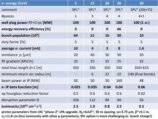
example parameters Example LHeC-RR and RL parameters.Numbers for LHeC-RL high-luminosity optionmarked by `†' assumeenergy recovery with hER=90%; those with `‡’ refer to hER=0%.ILC and XFEL numbers are included for comparison.Note that optimization of the RR luminosity for different LHCbeam assumptions leads to similar luminosity valuesof about 1033cm-2s-1
energy recovery - examples Jlab: recirculatinglinac, 99.5% of energy recovered at 150 MeV and 10 mA, ~98% recovery at 1 GeV and 100 mA with beam swung between 20 MeV to 1 GeV, plans for multi-GeVlinacswithcurrents of ~100 mA S. Chattopadhyay M. Tigner, “A possible apparatus for electron clashing-beam experiments,”Nuovo Cim.37:1228-1231 (1965). J. Sekutowicz et al, “Proposed continuous wave energy recovery operation of an XFEL,”Phys.Rev.ST Accel.Beams 8:010701,2005, up to 98% efficient return arc
energy recovery in UK’s ALICE ALICE tuned for transport of 20.8 MeV beam, 20 Dec. ’08. Green and dark blue traces show reduction to "zero" in RF demand on both linac cavities when beam is decelerated.
e+ for R-L LHeC a challenge: 10x more e+ than ILC! large # bunches → damping ring difficult candidate e+ sources under study (POSIPOL coll.): - spent e- beam impacting on target - crystal hybrid target source - ERL Compton source for CW operation e.g. 100 mA ERL w. 10 optical cavities - undulator source using spent e- beam - linac-Compton source for pulsed operation complementary options: collimate to shrink emittance, [extremely fast damping in laser cooling ring?,] recycle e+ together with recovering their energy? T. Omori, L Rinolfi, J. Urakawa et al talk by Louis Rinolfi tomorrow
some e+ source options Two methods to produce polarized e+ 1) helical undulator e- e- beam e- e+ • rays E = 10 -20 MeV e- E ~ 50-150 GeV e- L > 100 m e+ g 3) hybrid target (unpolarized) 2) Compton with laser Laser e+ e- beam thin crystal amorphous e- E = 1 - 6 GeV • rays E = 30 -60 MeV e+ Louis Rinolfi
e+ source trade offs #photons or #e- per pulse primary beam shape & energy target survival (options: multiple targets, hybrid, metal jet?) e+ rate & e+ emittance
early L-R e+ source studies • simulation of e+ production for 60 GeV e-beam hitting target • (Alessandro Vivoli) – next slide • Compton target heating limits (Alessandro Vivoli) • - next next slide • Linac Compton source parameters & LHeC optimization • (Igor Pogorelsky, VitalyYakimenko) – following four slides • Compton ERL or Compton ring (Louis Rinolfi) • talk tomorrow • spent beam undulator option (Louis Rinolfi) • talk tomorrow, and one slide • hybrid target option (Louis Rinolfi) – talk tomorrow
e+ from 60-GeV e- on target Alessandro Vivoli, June 2008 high yield; collimation could yield desired #e+ and sub-mm normalized emittance simulated e+ yield for amorphous W target of varying thickness hit by a 60-GeVe- beam [geee=20mm, sx,y,e=20 mm, b=10 m]
Compton-source target limit • Peak Energy Deposition Density <35 J/g per pulse • (W target survival); • each photon (E~27.7 MeV) deposits ~ 2.2x10⁻¹³ J/g • → limit of 1.6e14 photons per pulse on target; • e+/gamma yield ~ 2% • →maximum 3x10¹² e+ per “pulse” • normalized transverse emittance of ILC captured e+ • ~6500 micron; • yield proportional to emittance, so that limit = • e.g. 3x10⁹ e+/pulse with gex,y=200 mm (pulse~1 ms) • Compton e+ source might need stacking or recycling talk by Louis Rinolfi tomorrow Alessandro Vivoli, April 2009
ILC/CLIC linac Compton source Direct electron-gamma–positron sequence (no stocking) • ILC and CLIC: order 1 nC charge per e+ bunch. • Conversion efficiency of polarized g-photons into polarized e+ about 2%, optimized for 60% polarization. Every e+ requires 50 g-photons assembled in the same format (bunch length and repetition rate) as collider beams. • Proposal to accumulate this g-flux via Compton scattering at several consecutive IPs. In each IP, a 4.75-GeV e-beam undergoes a head-on collision with a CO2-laser pulse that produces one g-photon per electron x5 Ng/Ne-~1 10 nC Ne+/Ng~2% 1 nC example for ILC Igor Pogorelsky
linac Compton source linac Linac Compton Source for ILC (CLIC) example for ILC Igor Pogorelsky
ILC/CLIC CO2 laser parameters CO2 laser beam parameters at the Compton IP example for ILC Igor Pogorelsky
LHeClinac Compton source • multiple targets/capture (3-5) operating in parallel needed • ~30-50 g’s for 1 e+; ~10 g’s per e- (10% of the e-beam power converted to gammas in 10 laser IPs) • 5 GeV pulsed drive linac with ~ 5-10 nC e- bunches and 5 times average e+ current [main cost] • focus e- and g beam at target(not at the Compton IP); e- beam area will be ~4 times at Compton IP, compensated by ~4 times higher circulated laser energy (no showstopper) • resulting normalized emittanceeN~sq,e+ sgbeamge+ where • sq,e+ ~14 MeV/Ee+ sqrt(Ltarget/X0) ~ 20/ge+ • need sgbeam <5 mm on target; easy for 5 GeV e- beam • radiation damage of target material; liquid mercury jet? V. Yakimenko
undulator e+ source • using “spent” e- beam of 50-150 GeV energy • this might produce more photons & small • emittance more easily • option not yet explored, but can learn from CLIC • studies (Argonne contribution) • hoping for help from CI colleagues talk by Louis Rinolfi tomorrow
polarized beams e- : from polarized dc gun with ~90% polarization, 10-100 mm normalized emittance e+: up to ~60% from undulator or Compton-based source
polarized photo-cathode (e-) M. Kuriki
R-L LHeC physics merits • no interruption of LHC pp physics program • ep collisions at much higher energy & luminosity • than HERA • e- beam energy can be increased in stages, w/o • any fundamental limit • possibility of 90% e- and 60% e+ polarization • potential for large detector acceptance • additional possibility of g-por g-N collisions via • laser Compton back-scattering (this mode is • incompatible with energy recovery)
one staged schedule – E first 2025 2019 2021 2023 2028 2030 SLHC phase II 60 GeV, pulsed Lep~ 3x1032 m-2s-1 100 GeV, pulsed, ~2.2x1032 m-2s-1 only 40% of the linac are needed for first stage! 140 GeV, pulses, 1.5x1032 m-2s-1 60 GeV, cw, ER h~90% 3x1033 m-2s-1 new klystrons 60 GeV, cw, ER h~98%, 1.5x1034 m-2s-1 total electric wall-plug power 100 MW
2nd staged schedule – L first 2025 2019 2021 2023 2028 2030 SLHC phase II 60 GeV, cw, Lep~ 3x1032 m-2s-1 60 GeV, cw, ER h~90%, ~3x1033 m-2s-1 60 GeV, cw, ER h~98%, 1.5x1034 m-2s-1 the full linac is needed for first stage! 100 GeV, pulsed 2x1032 m-2s-1 new klystrons 140 GeV, pulsed, 1.5x1032 m-2s-1 total electric wall-plug power 100 MW