Download

1 / 9
90 likes | 272 Views
Resonant Circuit. The behavior of the series RLC circuit is governed by the impedance. Magnitude and phase. Series Behavior. i. R. L. v. C. There is special behavior when X C = X L . Vectors cancel Impedance only from resistor This is called resonance. Perfect Match. V L =IX L.

E N D
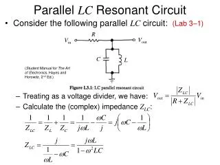
The behavior of the series RLC circuit is governed by the impedance. Magnitude and phase Series Behavior i R L v C
There is special behavior when XC = XL. Vectors cancel Impedance only from resistor This is called resonance. Perfect Match VL=IXL VR=IR VC=IXC
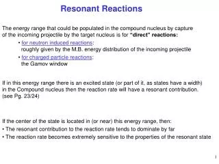
The requirements for resonance come from the reactances. There is a resonant frequency w0 associated with the circuit. Angular frequency w Can be converted into frequency f in Hz Resonant Frequency
The total impedance is the magnitude of Z. The phase between the current and voltage is the angle f between Z and the x-axis. Vector Sum XL XC Z f R
Peak Performance • At resonance the current is at maximum for the voltage.
The problem requires the formula for the frequency f. Only the inductance and capacitance matter. 1/2p (0.25 H 10-7 F)1/2 = 1 kHz Find the resonant frequency in the following circuit in Hz. Circuit Example 100 W 250 mH 10 V 0.1 mF
The behavior of the series RLC circuit is governed by the impedance. Magnitude and phase Circuit Example 100 W 250 mH 10 V 0.1 mF
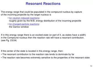
In the preceding circuit the voltage across each component can be found. Current due to resistor only The voltage across the inductor has an amplitude of 158 V. So does the capacitor They are each 90° out of phase and cancel out. Resonant Reactance next