Download
1 / 44
1.29k likes | 3.78k Views
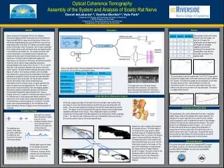
Introduction: Optical coherence tomography. Peter E. Andersen Optics and Plasma Research Department Risø National Laboratory, Denmark E-mail: peter.andersen@risoe.dk. Outline. Part I: Introduction to optical coherence tomography (OCT). Part II:

E N D
Introduction:Optical coherence tomography Peter E. Andersen Optics and Plasma Research Department Risø National Laboratory, Denmark E-mail: peter.andersen@risoe.dk
Outline • Part I: • Introduction to optical coherence tomography (OCT). • Part II: • Modeling the light propagation in the OCT geometry. • Part III: • Biomedical applications, • Extracting optical properties. Peter E. Andersen, Optics and Plasma Research Department
Outline – Part I • Physical principle behind OCT • based on interference, • tomography comes about by scanning. • Components and systems Peter E. Andersen, Optics and Plasma Research Department
Optical biopsy – definition • The in situ imaging of tissue microstructure with a resolution approaching that of histology, but without the need for tissue excision and processing Peter E. Andersen, Optics and Plasma Research Department
Optical coherence tomography • Three-dimensional imaging technique with ultrahigh spatial resolution even in highly scattering media • Based on measurements of the reflected light from tissue discontinuities • e.g. the epidermis-dermis junction. • Based on interferometry • involves interference between the reflected light and the reference beam. Peter E. Andersen, Optics and Plasma Research Department
Resolution (log) 1 mm Ultrasound 100 mm 10 mm Confocalmicroscopy 1 mm Penetration depth (log) 1 mm 1 cm 10 cm OCT vs. standard imaging Standardclinical Highfrequency OCT Peter E. Andersen, Optics and Plasma Research Department
Ophthalmology diagnosing retinal diseases. Dermatology skin diseases, early detection of skin cancers. Cardio-vascular diseases vulnerable plaque detection. Endoscopy (fiber-optic devices) gastrology, … Functional imaging Doppler OCT, spectroscopic OCT, optical properties, PS-OCT. OCT in non-invasive diagnostics • Guided surgery • delicate procedures • brain surgery, • knee surgery, • … Peter E. Andersen, Optics and Plasma Research Department
The OCTsetup Fiber-optic beamsplitter Broadband source Tissue Scanning reference mirror Detector Computer Amplifier Bandpass filter Peter E. Andersen, Optics and Plasma Research Department
Interference Coherent source Michelson interferometer light source Detector Partially coherent source Peter E. Andersen, Optics and Plasma Research Department
Construction of image Peter E. Andersen, Optics and Plasma Research Department
Normal Eye 250 microns Humphrey Nominal width of scan: 2.8 mm Peter E. Andersen, Optics and Plasma Research Department
UHR-OCT versus commercial OCT W. Drexler et al., “Ultrahigh-resolution ophthalmic optical coherence tomography”, Nature Medicine 7, 502-507 (2001) Peter E. Andersen, Optics and Plasma Research Department
The OCTsetup Fiber-optic beamsplitter Broadband source Tissue Scanning reference mirror Detector Computer Amplifier Bandpass filter Peter E. Andersen, Optics and Plasma Research Department
System perspective (links clickable) • Light sources • Superluminescent diodes • Semiconductor amplifiers • Femtosecond lasers • … • Beam delivery and probes • Hand-held probe • Catheter • Ophthalmoscope • Microscope • OCT imaging engine • Resolution • Reference delay scanning • Doppler/polarization/spectroscopy • Detection • Frequency domain continue • Computer control • Drive system • Real-time display • Data management • Image & signal processing • Motion reduction • Speckle reduction • Image enhancement • Rendering algorithms • … Peter E. Andersen, Optics and Plasma Research Department
Choosing the light source • Four primary considerations • wavelength, • bandwidth, • power (in a single-transverse-mode), • stability; • portability, ease-of-use, etc. Peter E. Andersen, Optics and Plasma Research Department
Choose light source – wavelength Peter E. Andersen, Optics and Plasma Research Department
Choose light source – wavelength • Light propagation (Monte Carlo simulation) Absorption “Snake” component Incident light Ballistic component Diffuse reflectance Diffuse transmittance Peter E. Andersen, Optics and Plasma Research Department
Choose light source – wavelength Peter E. Andersen, Optics and Plasma Research Department
Raw signals • Scattering mainly attenuates the signal Peter E. Andersen, Optics and Plasma Research Department
Light source spectrum • Basic property • the temporal coherence envelope function G(t) is related to the power spectral function S(n) through G(t) = FT{S(n)} • Wiener-Kinchine theorem • broadband source high axial resolution Peter E. Andersen, Optics and Plasma Research Department
Source spectrum and envelope Peter E. Andersen, Optics and Plasma Research Department
Axial resolution • The axial resolution is • notice that Dl is the 3dB-bandwidth! Peter E. Andersen, Optics and Plasma Research Department
Plotting the relation Peter E. Andersen, Optics and Plasma Research Department
Light sources for OCT (1/2) • Continuous sources • SLD/LED/superfluorescent fibers, • center wavelength; • 800 nm (SLD), • 1300 nm (SLD, LED), • 1550 nm, (LED, fiber), • power: 1 to 10 mW (c.w.) is sufficient, • coherence length; • 10 to 15 m (typically), • Example • 25 nm bandwidth @ 800 nm 12 m coherence length (in air). Peter E. Andersen, Optics and Plasma Research Department
Light sources for OCT (2/2) • Pulsed lasers • mode-locked Ti:Al2O3 (800 nm), • 3 micron axial resolution (or less). • Scanning sources • tune narrow-width wavelength over entire spectrum, • resolution similar to other sources, • advantage that reference arm is not scanned, • advantage that fast scanning is feasible. Peter E. Andersen, Optics and Plasma Research Department
OCT spatial resolution • Axial and lateral resolutions are decoupled • The axial resolution is • notice that Dl is the 3dB-bandwidth! • The lateral resolution is determined by the focusing conditions • optics • dynamic vs. static focusing Peter E. Andersen, Optics and Plasma Research Department
Plotting the relation Peter E. Andersen, Optics and Plasma Research Department
Low NA Lateral resolution High NA Dz Dz Dz Dz b b Depth of focus Lateral resolution (1/2) Peter E. Andersen, Optics and Plasma Research Department
Lateral resolution (2/2) Peter E. Andersen, Optics and Plasma Research Department
Ultra-high resolution OCT • Broad bandwidth sources • solid-state lasers, • sub-5 fs pulse; • Ti:Al2O3 (Spectral bandwidth: 350 nm demonstrated), • other lasers/wavelengths available or needed. • Special interferometers and fiber optics • support for broad spectral range, • dispersion balanced, • current system used for OCT: 260 nm bandwidth, ~1.5µm resolution. • Chromatically corrected optics • aberrations can decrease resolution and SNR. • Broad bandwidth detectors and electronics • dual balance detection, • low noise circuitry necessary. Peter E. Andersen, Optics and Plasma Research Department
Scanning devices • Piezo or motorized scanning devices • ideal for both longitudinal and lateral scanning. • Galvanic mirrors • Resonance scanners • Helical mirrors • longitudinal scanning. • Fiber stretcher • longitudinal scanning. Peter E. Andersen, Optics and Plasma Research Department
Fourier domain rapid scanning optical delay line (RSOD) • The technique was originally developed for femtosecond pulse measurements • based on Fourier-transform pulse shaping techniques. • Relies on the basic property of the Fourier transform • phase ramp in the Fourier domain corresponds to a group delay in the time domain. Peter E. Andersen, Optics and Plasma Research Department
RSOD setup Peter E. Andersen, Optics and Plasma Research Department
RSOD in the lab Peter E. Andersen, Optics and Plasma Research Department
Free-space group pathlength p: the grating pitch, f: focal length, s: mirror angle. Interferogram central frequency Bandwidth RSOD characteristics Peter E. Andersen, Optics and Plasma Research Department
RSOD – figures-of-merit • Scanning capabilities (galvo) • 200 Hz, • 5 mm. • Scanning capabilities (resonant) • 4-8 kHz, • 5 mm. • Advantages • dispersion compensation feasible since phase and group delays may be separated, • center frequency of interferogram is adjusted through axial position. Peter E. Andersen, Optics and Plasma Research Department
Light propagation in sample • The sample • need to describe light-tissue interaction taking temporal and spatial coherence properties into account; • can transport theory be used? • Light-tissue interaction to be modelled using the extended Huygens-Fresnel principle • Part II of this lecture, • correlation between tissue, state of tissue (lesions) and optical properties? • Part III of this lecture. Peter E. Andersen, Optics and Plasma Research Department
Our setup (mobile OCT unit) Peter E. Andersen, Optics and Plasma Research Department
Clinically adapted systems Peter E. Andersen, Optics and Plasma Research Department
BCC II • Layers • Thinning oflayers L. K. Jensen, MSc thesis (in Danish), 2003 [data obtained atLund Medical Laser Centre, courtesy K. Svanberg]. Peter E. Andersen, Optics and Plasma Research Department
Dynamic range 100 dB (or better). Resolution (typical) 1-10 micrometers. Penetration depth depending on wavelength/tissue, 1-2 mm (typically) for 1300 nm in skin tissue. Axial and lateral resolutions are decoupled important for applications. Pixel density is related to spatial resolution and image acquisition time Nz=2*Lz/dz, Nx=2*Lx/dx, image acq. time: T=Nx*fs, scan velocity: vs=Lz*fs. Image acquisition seconds or less, real-time OCT. Clinical adaptation interfaced to standard equipment, fiber-optic devices, endoscopes. OCT: Figures-of-merit – summary Peter E. Andersen, Optics and Plasma Research Department
Ophthalmology diagnosing retinal diseases. Dermatology skin diseases, early detection of skin cancers. Cardio-vascular diseases vulnerable plaque detection. Endoscopy (fiber-optic devices) gastrology, … Functional imaging Doppler OCT, spectroscopic OCT, optical properties, PS-OCT. OCT in non-invasive diagnostics • Guided surgery • delicate procedures • brain surgery, • knee surgery, • … Peter E. Andersen, Optics and Plasma Research Department
OCT: suggested reading • OCT • D. Huang et al., Science 254, 1178 (1991) • A. Fercher, J. Biomed. Optics 1, 157 (1996) • J. M. Schmitt, “Optical coherence tomography (OCT): A review”, IEEE J. Select. Topics Quantum Electron. 5, 1205-1215 (1999) • J. G. Fujimoto et al., “Optical coherence tomography: An emerging technology for biomedical imaging and optical biopsy”, Neoplasia 2, 9-25 (2000) • W. Drexler et al., “Ultrahigh-resolution ophthalmic optical coherence tomography”, Nature Medicine 7, 502-507 (2001) • W. Drexler, “Ultrahigh-resolution optical coherence tomography”, J. Biomed. Opt. 9, 47-74 (2004) Peter E. Andersen, Optics and Plasma Research Department