Download

1 / 41
410 likes | 427 Views
Learn about Frame Relay network operations, terminology, and configurations to establish efficient connections between routers and switches. Understand the OSI layered model, protocols, topologies, and key concepts.

E N D
Chapter 10Establishing Frame RelayConnections Frame Relay Overview Configuring Frame Relay
Frame Relay Overview • Frame Relay 네트워크의 작용과 기능을 이해한다. • Frame Relay 의 여러 가지 용어를 이해한다.
DCE or FrameRelay switches CSU/DSU Frame Relayworks here * Introducing Frame Relay Frame Relay Overview • 프레임 릴레이는 데이터를 전송하기 위한 과정을 정의하는 ITU-T, ANSI의 표준이다. • 프레임 릴레이는 Layer 2 Protocol이면서, Virtual circuit을 사용하여 연결한다. • Connection-oriented Service를 제공한다. • 프레임 릴레이는 라우터와 서비스 제공업체의 로컬 액세스 스위칭 장비 사이의 연결 과정을 정의한다. • 프레임 릴레이는 연결 식별자들을 단일 물리 전송 링크에서 많은 논리적인 가상회선들을 통계적으로 다중화하는 수단을 제공한다. • 서비스 제공업체의 스위칭 장비는 연결 식별자를 출력 포트에 맵핑하는 테이블을 만든다.
* Frame Relay Stack Layered Support Frame Relay Stack OSI Reference Model Frame Relay Application Presentation Session Transport IP/IPX/AppleTalk, etc. Network Data Link Frame Relay EIA/TIA-232, EIA/TIA-449, V.35, X.21, EIA/TIA-530 Physical • Frame Relay 는 Data Link Layer에서 작동한다. • Frame Relay 는 Multiple Upper-Layer Protocol을 지원한다. • OSI 스택의 상위 계층에서부터 오는 정보를 캡슐화한다.
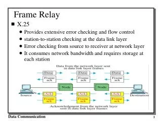
Frame Relay Format • opening flags (0x7E) • Address : 10bits circuit identifier, 6bits congestion management • Data : encapsulated upper-layer data • FCS (frame check sequence) : 에러 check 기능 • closing flags (0x7E)
PVC Router A Router B DLCI:100 DLCI:200 LMI 100 = Active 400 = Active Branch Branch Central Local Access Loop = 64 Kbps DLCI:400 Local Access Loop = T1 PVC Local Access Loop = 64 Kbps DLCI:500 Router C * Frame Relay Terminology Frame Relay Terminology
Frame Relay Terminology (Cont.) • 프레임 릴레이 용어 • Local Access Rate : Frame Relay Cloud 연결에서의 Clock Speed 를 말한다. • 가상회선(VC) : 두 개의 네트워크 디바이스간의 통신을 보장하기 위해서 만들어지는 논리 적인 회선. 가상회선은 PVC or SVC가 될 수 있다. • PVC(Permanent Virtual Circuit) : 영구적으로 설정되는 가상회선 • SVC(Switched Virtual Circuit) : 요구에 의해서 동적으로 설립되고 전송이 끝날 때 해제되는 가상회선. SVC는 데이터 전송이 가끔씩 일어나는 상황에서 사용된다. • DLCI(Data-Link Connection Identifier) : 라우터와 프레임릴레이 스위치 사이의 논리적인 회선을 식별하는 번호이다. 프레임 릴레이 스위치는 PVC를 만들기 위해서 라우터 쌍에 DLCI를 할당한다. • CIR(Common Information Rate) : Frame Relay Switch의 최소 보장 Transfer Rate이다. Service provider는 CIR 값을 넘어서는 Packet Burst를 허용한다. CIR를 넘어서는 Packet Burst는 유사시에 버려 질 수 있다. • Oversubscription : access line speed를 넘어서 Packet을 전송되는 것을 말한다.
Frame Relay Terminology (Cont.) • 프레임 릴레이 용어 • Be(Excess Burst) : CIR을 넘어서 Frame Relay Switch가 Transfer하는 Rate이다. • Bc(Committed Burst) : Frame Relay Switch 가 Transfer 해 줄 수 있는 최대 Transfer Rate이다 • DE(Discard Eligibility) : Router가 CIR을 넘어서는 Traffic에 대해서 설정하는 bit로 , Network Congestion의 경우, FR Switch는 DE bit가 설정된 Packet을 먼저 drop 시킨다. • IARP(Inverse Address Resolution Protocol) : 네트워크 계층 주소를 DLCI와 동적으로 연관시키는 방법이다. 이것은 라우터가 VC와 연관된 디바이스의 네트워크 계층 주소를 발견하도록 한다. • LMI(Local Management Interface) : 라우터 와 F/R Switch간의 연결과 유지 상태를 관리하는 책임을 가지는 F/R간의 시그널링 표준이다. • FECN(Forward Explicit Congestion Notification) : frame relay switch가 congestion을 인지한 경우, Destination Device에 보내는 Message이다. • BECN(Backward Explicit Congestion Notification) :frame relay switch가 congestion을 인지한 경우, Source Router에 보내는 Message이다.
Full mesh Partial mesh Star (hub and spoke) * Frame Relay Topologies Selecting a Frame Relay Topology
Selecting a Frame Relay Topology (cont.) • Star topology : hub-and-spoke 설정으로도 알려져 있는 것으로 가장 일반적인 프레임 릴레이 네트워크 토폴로지이다. 원격 사이트가 중앙 사이트에 연결되어 서비스 또는 응용을 제공한다. 이것은 최소의 PVC 개수를 필요로 하기 때문에 가장 저렴한 토폴로지이다. • Full-mesh topology : 모든 라우터는 모든 다른 목적지에 대해서 가상 회선을 가진다. 비용은 많이 들지만, 각 사이트에서 모든 다른 사이트로의 직접 연결이 제공되어서 예비 경로를 마련해 준다. 한 링크가 다운되었을 때, 라우터는 트래픽을 다른 사이트를 통해서 우회시킬 수 있다. • Partial-mesh topology : 모든 사이트들이 다른 모든 사이트로 직접 액세스할 수는 없다. 네트워크 트래픽 패턴에 따라서, 많은 데이터 트래픽 요구사항을 가지는 원격 사이트로 연결되는 추가적인 PVC를 만들 수 있다.
Routingupdate Circuit #21 1 B B Circuit #22 2 A C C Circuit #23 3 D D * Resolving Reachability Issues in Frame Relay Reachability Issues with Routing Updates 10.16.0.2 10.16.0.1 10.16.0.3 10.16.0.4 • Frame Relay issues • Broadcast traffic은 모든 Active connection에 복제 되어야 한다. • 프레임 릴레이가 단일 인터페이스에서 여러 PVC를 작동시키고 있다면, 주된 문제는 Split horizon이다
Reachability Issues with Routing Updates (cont.) • Frame Relay Network 은 Nonbroadcast Mulitaccess (NBMA) network이다. - 프레임 릴레이 스위치는 단일 DLCI로 부터 들어오는 브로드캐스트 패킷을 모든 DLCI 로 복제하지 않기 때문에 nonbroadcast라고 부른다. • Frame Relay Interface는 Multipoint Connection을 지원한다. PVC간에 Broadcast가 되지 않는 관계로 Multiple PVC가 하나의 Interface에 연결되는 경우는 라우터간에 발생하는 Routing Update에 문제가 생긴다. 하나의 Interface에 하나의 PVC만을 사용 하는 경우에는 문제가 없다. • Split horizon은 한 인터페이스에서 수신된 라우팅 업데이트가 동일한 인터페이스 포워드 되지 않게 함으로써 라우팅 루프를 줄이게 된다. • Full Mesh Topology가 아닌 Frame Relay network에서는 Split Horizon으로 발생하는 Routing Update 문제에 대한 조치를 하여야 한다. • Split Horizon에 대한 Solution은 Frame Relay network에 연결된 Physical Interface를 logical subinterface로 나누는 것이다. • Physical Interface는 여러 개의 Logical Interface로 나누어 질 수 있다.
Physicalinterface Subnet A Logical interface 10.1.1.2/24 10.1.1.1/24 S0 Subnet B S0.1 10.2.2.1/24 S0.2 10.3.3.1/24 10.2.2.2/24 S0.3 Subnet C 10.3.3.2/24 Resolving Reachability Issues • Split horizon이 발생시킨 Routing update 문제해결 • 네트워크를 Full Mesh topology로 구축한다. • Split horizon을 disable 시키는 것은 라우팅 루프 발생 확률이 높기 때문에 권장하는 방법은 아니다. • 브로드캐스트 라우팅을 업데이트 하기 위해서는 서브인터페이스(subinterface) 라고 부르는 논리적으로 할당된 인터페이스를 라우터에 설정해야 한다. • Subinterface는 하나의 Physical interface를 여러 개의 Logical interface로 나눈 것다. • 한 subinterface에서 수신된 라우팅 업데이트들은 다른 서브인터페이스로 전송될 수 있다.
CSU/DSU FrameRelay Destination DLCI (500) IP(10.1.1.1) * Frame Relay Address Mapping Frame Relay Address Mapping PVC 10.1.1.1 DLCI=500 Inverse ARP orFrame Relay map • Frame Relay Provider로부터 DLCI 번호를 할당 받는다. • 라우터가 원격지에 도착하기 위해서는 각 VC에 연관된 주소를 알아야 한다. • DLCI는 각 VC를 식별한다. • Network Addresses를 DLCI번호와 Mapping한다. • Inverse ARP는 local DLCI와 remote 라우터의 IP 주소와 자동으로 맵핑한다.
LMI 500=Active400=Inactive DLCI=500 PVC 10.1.1.1 CSU/DSU DLCI=400 PVC Keepalive * Frame Relay Signaling Frame Relay Signaling • LMI(Logical Management Interface) : Frame Relay Switch(DCE)와 Router(DTE)간의 Signaling 표준으로 두 디바이스간의 상태를 유지 및 관리한다. LMI Message에는 VC의 상태를 알리는 메시지, 데이터 흐름을 확인하는 Keep Alive Message, 멀티캐스트 메커니즘 등에 대한 지원을 포함한다. • LMI 표준 3가지 (한가지를 선택해서 수동으로 설정해 주어야 한다.) • ansi : ANSI 표준 T1.617 에 의해 정의된다. • q933a : ITU-T 표준 • cisco : 시스코에 의해 정의된 LMI 타입 • 라우터가 LMI 정보를 수신하게 되면, VC는 다음 중 하나로 업데이트 된다. • Active : 연결이 활성화 되고 라우터가 데이터를 교환할 수 있다 • Inactive : F/R 스위치에 대한 로컬 연결은 작동 중이지만, 라우터의 연결은 작동하지 않음 • Deleted : F/R 스위치로부터 어떤 LMI도 수신하지 못했고, 서비스도 없다는 것을 가리킴
1 2 3 2 3 4 Frame Relay Cloud DLCI=400 DLCI=100 172.168.5.5 172.168.5.7 Status Inquiry Status Inquiry Local DLCI 100=Active Local DLCI 400=Active Hello, I am 172.168.5.5 Frame Relay Inverse ARP and LMI Signaling • 1단계 : 라우터는 CSU/DSU를 통해 프레임 릴레이 스위치와 연결된다. • 2단계 : F/R이 인터페이스에 설정되면, 라우터는 상태 질문 메시지를 F/R 스위치에 전송한다. 메시지는 스위치에 라우터의 상태를 알려주고 라우터에 라우터의 VC의 연결 상태를 물어보게 된다. • 3단계 : 라우터는 원격 라우터에 대한 PVC의 DLCI등 상태 메시지를 스위치에게 보냄 • 4단계 : 각 활성화된 DLCI에 대해서, 각 라우터는 자기를 소개하는 IARP 패킷을 전송
5 7 7 5 4 6 Frame Relay Cloud DLCI=400 DLCI=100 172.168.5.5 172.168.5.7 Stages of Inverse ARP and LMI Operation Hello, I am 172.168.5.7 Hello, I am 172.168.5.5 Keepalives Keepalives • 5단계 : 라우터가 IARP 메시지를 수신할 때, 로컬 DLCI와 원격지 IP로 맵 테이블을 만든다. • 6단계 : 매 60초마다 라우터는 모든 활성화된 DLCI를 역 ARPA 메시지에 전송한다. • 7단계 : 매 10초마다 라우터는 스위치와 LMI 정보를 교환한다.(Keepalive) 라우터는 F/R 스위치의 응답에 기초해서 각 DLCI 상태를 바꾼다.
Service Provider Network Sydney SYD 9.4.7=KYO 5.3.2 TOK 1.3.4=MEL 1.2.9 Branch Tokyo MEL1.2.9=TOK 1.3.4 Melbourne KYO 5.3.2=SYD 9.4.7 Kyoto * How Service Providers Map Frame Relay DlCIs How Service Providers Map Frame Relay DLCIs : Service Provider • 스위치는 inbound DLCI 값을 확인한다. • 스위치는 로컬 DLCI 값과 대비되는 원격지 DLCI의 값을 확인한다. • 스위치는 이두 DLCI 값을 F/R header에 포함해서, 적당한 switch.slot.port로 프레임을 전송한다.
Sydney Service Provider Network DLCI 112 DLCI 411 Branch Tokyo DLCI 114 Melbourne DLCI 211 Kyoto How Service Providers Map Frame Relay DLCIs : Enterprise • 위 그림은 원격 라우터에 일치하는 DLCI 값을 얻기 위해 역DLCI 값을 사용하는 것을 보여 준다. • Melbourne은 단순하게 DLCI 411을 사용하는 Tokyo로 부터 프레임이 도착 했다는 것을 알 수 있다.
Service Provider Frame Relay-to-ATM Interworking DLCI VPI/NCI VPI/NCI DLCI 192 0/96 0/96 107 FRF.5 Internetworking Function FRF.5 Internetworking Function ATM PVC ATM PVC ATM Network DLCI = 192 DLCI = 107 Frame Relay PVC Frame Relay PVC Frame Relay End Station Frame Relay End Station • Frame Relay-to-ATM은 Frame Relay 와 ATM네트워크의 연속성을 제공한다. • 현재의 Frame Relay 사용자를 위해 명시적으로 개발된 두 이행 동의는 Network Interworking (FRF.5)과 Service Interworking이다. (FRF.8). • FRF.5는 Frame Relay가 FRF.5를 지원하는 중간의 ATM 네트워크 위로 통신하는 사용자를 허락하는 네트워크 interworking 기능성을 제공한다. • Multiprotocol 캡슐로 봉하기와 다른 higher-layer 과정은 ATM 네트워크 위로 투명하게 수송된다.
FRF.8 Internetworking Function ATM PVC ATM End Station Frame Relay End Station Frame Relay PVC FRF.8 Service Interworking • FRF.8 은 Frame Relay 사용자와 ATM 사용자 사이의 통신을 허용한다. • FRF8 은 서로 다른 Frame Relay와 ATM 설비 사이에 전송되는 트래픽의 변환을 담당한다. • Frame Relay-to-ATM을 설정할 때에는 인터페이스에 Frame Relay로 설정한다.
Configuring Frame Relay • Frame Relay PVC를 설정할 수 있다. • Show 명령어를 통해 Frame Relay의 작용과 기능을 이해한다. • debug 명령어를 통해 Frame Relay의 작용과 기능을 이해한다.
Cisco IOS Release 12.0 Router Cisco IOS Release Prior to 11.2 Branch HQ * Configuring a Basic Frame Relay Network Configuring Basic Frame Relay Interface serial 1 ip address 10.16.0.1 255.255.255.0 encapsulation frame-relay bandwidth 64 frame-relay lmi-type ansi Interface serial 1 ip address 10.16.0.2 255.255.255.0 encapsulation frame-relay bandwidth 64 frame-relay lmi-type ansi
DLCI=110 IP Address=10.16.0.1/24 Branch HQ DLCI=100 IP Address=10.16.0.2/24 * Configuring a Static Frame Relay Map Configuring a static Frame Relay Map Interface serial 1 ip address 10.16.0.1 255.255.255.0 encapsulation frame-relay bandwidth 64 frame-relay map ip 10.16.0.2 110 broadcast
Configuring a static Frame Relay Map (cont.) • Router(config-if)#frame-relay map protocol protocol-address dlci [broadcast] [ietf | cisco][payload-compress packet-by-packet] • protocol : IP, IPX, Appletalk 등 지원되는 프로토콜, 브리징, 논리적 링크 제어를 정의한다. • Protocol-address : 목적지 라우터 인터페이스의 네트워크 계층 주소를 정의한다. • DLCI : 원격 프로토콜 주소에 연결되기 위해 사용되는 로컬 DLCI를 정의한다. • Broadcast : VC로 브로드캐스트와 멀티캐스트를 포워딩하는 옵션이다. 이것은 VC에서 동적인 라우팅 프로토콜을 허용한다. • ietf | Cisco : IETF 또는 Cisco 캡슐화를 enable 한다. • payload-compress packet-by-packet : STAC 방법을 이용해서 packet-by- packet payload 압축을 enable하는 옵션이다. 이것은 Cisco 전용 압축 방법이다.
* Configuring Frame Relay Subinterfaces Configuring Subinterfaces • Point-to-Point (점대점) : - 단일 서브인터페이스가 한 PVC를 다른 물리 인터페이스 또는 원격지 라우터의 서브인터페이스에 연결하도록 한다. - 이 경우에 인터페이스는 동일한 서브넷에 있게 되고, 각 인터페이스는 단일 DLCI를 가지게 될 것이다. - 각 점대점 연결은 독자적인 서브넷이다. - 라우터가 점대점이고 전용선과 같이 작동하기 때문에 브로드캐스트는 문제가 없다. - hub and spoke topologies에 적합하다. • Multipoint(다중 지점) : - 단일 서브인터페이스는 여러 PVC를 원격 라우터의 여러 물리 인터페이스 또는 서브인터페이스로 연결하는 데 사용된다. - 이 경우에는 관계되는 인터페이스는 동일한 서브넷에 있게 되고, 각 인터페이스는 독자적인 DLCI를 가지게 될 것이다. - 이 환경에서는 서브인터페이스는 NBMA 프레임 릴레이 인터페이스처럼 행동하기 때문에 브로드캐스트 트래픽은 split horizon 규칙에 해당된다. - partial mesh and full mesh topologies에 적합하다.
10.17.0.1s0.2 DLCI=110 10.17.0.2 A s0.3 10.18.0.1 B DLCI=120 10.18.0.2 C Configuring Point-to-Point Subinterfaces interface Serial0 no ip address encapsulation frame-relay ! interface Serial0.2 point-to-point ip address 10.17.0.1 255.255.255.0 bandwidth 64 frame-relay interface-dlci 110 ! interface Serial0.3 point-to-point ip address 10.18.0.1 255.255.255.0 bandwidth 64 frame-relay interface-dlci 120 • 각각의 Subinterface에 대하여 해당 dlci값을 반드시 할당한다. • 각각의 point-to-point connection은 각각의 subnet을 필요로 한다. • 각 서브인터페이스는 독립된 물리 인터페이스처럼 처리되어 split horizon에 영향을 받지 않는다.
Configuring Point-to-Point Subinterfaces (cont.) • 1단계 : 서브인터페이스를 만들고자 하는 인터페이스를 선택하고, 인터페이스 설정 모드로 들어간다. • 2단계 : 물리 인터페이스에 할당된 네트워크 계층 주소는 삭제하고 서브인터페이스 네트워크 계층 주소를 할당하는 것을 권고한다. • 3단계 : Frame-Relay encapsulation을 설정한다. • 4단계 : 다음 명령어를 이용해서 설정하고자 하는 서브인터페이스를 선택한다. Router(config)#interface serial number. Subinterface-number {multipoint|point- to-point} - number.subinterface-number는 서브인터페이스 번호이다. 마침표 앞의 수는 물리 인터페이스 번호이고 뒤의 수는 서브인터페이스 수이다. - multipoint : ip를 라우팅하고 동일한 모든 라우터가 서브넷에 있기를 원한다면 선택 - point-to-point : 점대점 라우터의 각 쌍이 각자의 서브넷을 이루기를 원한다면 선택 • 5단계 : 서브인터페이스를 점대점이라고 설정했다면, 물리 인터페이스와 구분하기 위해서 서브인터페이스에 대한 로컬 DLCI를 설정해야 한다. Router(config-if)#frame-relay interface-dlci dlci-number - dlci-number : 서브인터페이스와 링크된 로컬 DLCI 번호를 정의한다. 이것은 LMI로 유도된 PVC가 서브인터페이스에 링크될 수 있는 유일한 방법이다.
RTR1 RTR3 RTR4 Multipoint Subinterface Configuration Example B DLCI=120 s2.2=10.17.0.1/24 s2.1=10.17.0.2/24 DLCI=130 DLCI=140 s2.1=10.17.0.3/24 interface Serial2 no ip address encapsulation frame-relay ! interface Serial2.2 multipoint ip address 10.17.0.1 255.255.255.0 bandwidth 64 frame-relay map ip 10.17.0.2 120 broadcast frame-relay map ip 10.17.0.3 130 broadcast frame-relay map ip 10.17.0.4 140 broadcast s2.1=10.17.0.4/24 • 하나의 Multipoint Subinterface를사용하므로 IP Address와 DLCI Map을 설정해 준다. • 하나의 subnet을 필요로 한다. NBMA이고 split-horizon 작동에 영향을 받을 수 있다. • Split-horizon은 기본적으로 F/R multipoint main interface에서는 disabled 되고subinterface에서는 enable 된다.
Router#show frame-relay traffic • Frame-relay traffic 상태를 보여준다. Router#clear frame-relay-inarp • inverse arp를 사용하여 동적으로 생성된, Frame-relay 맵을 초기화 한다. Router#show interface type number • Frame-relay DLCI와 LMI 정보를 보여준다. Router#show frame-relay lmi [type number] • Frame-relay LMI 상태를 보여준다. Router#show frame-relay map • Frame-relay map 테이블을 보여준다. Router#show frame-relay PVC [ type number] • Frame-relay PVC 상태를 보여준다. * Verifying Basic Frame Relay Operations Verifying Frame Realy Operation
Show interfaces Example Router#show interface serial 0 Serial0 is up, line protocol is up Hardware is CD2430 in sync mode MTU 1500 bytes, BW 128 Kbit, DLY 20000 usec, rely 255/255, load 1/255 Encapsulation FRAME-RELAY, loopback not set, keepalive set (10 sec) LMI enq sent 112971, LMI stat recvd 112971, LMI upd recvd 0, DTE LMI up LMI enq recvd 0, LMI stat sent 0, LMI upd sent 0 LMI DLCI 1023 LMI type is CISCO frame relay DTE FR SVC disabled, LAPF state down Broadcast queue 0/64, broadcasts sent/dropped 32776/0, interface broadcasts 14 Last input 00:00:00, output 00:00:03, output hang never Last clearing of "show interface" counters never Input queue: 0/75/0 (size/max/drops); Total output drops: 0 Queueing strategy: weighted fair <Output Omitted> • Show interface 명령어는 Layer 1, 2의 상태에 관한 정보를 보여준다. • 또한 LMI type, LMI DLCI, DTE/DCE type, 등을 보여준다. • Cisco Router는 Frame relay switch로 사용 가능하다. 이러한 경우에는 DCE가 된다. ( 뒷면 LAB Test (1) 참조)
Show frame-relay lmi Example Router#show frame-relay lmi LMI Statistics for interface Serial0 (Frame Relay DTE) LMI TYPE = CISCO Invalid Unnumbered info 0 Invalid Prot Disc 0 Invalid dummy Call Ref 0 Invalid Msg Type 0 Invalid Status Message 0 Invalid Lock Shift 0 Invalid Information ID 0 Invalid Report IE Len 0 Invalid Report Request 0 Invalid Keep IE Len 0 Num Status Enq. Sent 113100 Num Status msgs Rcvd 113100 Num Update Status Rcvd 0 Num Status Timeouts 0 • show frame-relay lmi 명령어는 LMI 트래픽 통계를 보여준다. • 로컬 라우터와 프레임 릴레이 스위치간에 교환되는 상태 메시지의 개수를 보여준다.
Show frame-relay PVC Example Router# show frame-relay pvc 100 PVC Statistics for interface Serial0 (Frame Relay DTE) DLCI = 100, DLCI USAGE = LOCAL, PVC STATUS = ACTIVE, INTERFACE = Serial0 input pkts 14055 output pkts 32795 in bytes 1096228 out bytes 6216155 dropped pkts 0 in FECN pkts 0 in BECN pkts 0 out FECN pkts 0 out BECN pkts 0 in DE pkts 0 out DE pkts 0 out bcast pkts 32795 out bcast bytes 6216155 PVC create time 00;03;46 last time PVC status changed 00;03;47 • Frame Relay operation과 Remote Router와의 연결 상태를 보여준다. • PVC traffic 통계를 보여준다. • 라우터에 수신된 BECN, FECN 패킷을 보는 데에도 유용하다. • PVC Status • Active state : 라우터간에 정보를 교환할 수 있는 정상적인 상태이다. • Inactive state : Local 라우터에서 스위치 오피스까지 에는 이상이 없으나 Remote • 라우터가 응답이 없는 상태이다. • Deleted state : Local Router와 스위치간에 LMI Information이 없는 경우이다.
Show frame-relay map Example Router# show frame-relay map Serial0 (up): ip 10.140.2.1 dlci 100(0x64, 0x1840), dynamic, broadcast,, status defined, active • show frame-relay map은 연결에 대한 현재의 map 엔트리와 정보를 보여준다. • 역 ARP 엔트리를 학습했는지 뿐만 아니라 설정된 정적 맵 엔트리를 보여준다. - 100 : 10진수의 DLCI 번호이다. - 0x64 : 16진수 표현이다. (0x64 = 십진수100) - 0x1840 : Frame relay address field에 나타나는 DLCI 값 - 10.140.1.1 : 원격 라우터 IP 주소(IARP에 의해 동적으로 배운 주소이다.) - Broadcast/multicast는 PVC 상에서 enabled 되어 있다. - PVC 상태는 active 이다. Router# sh frame map Serial0 (up): ip 10.140.2.1 dlci 100(0x64,0x1840), dynamic, broadcast,, status defined, active Router#clear frame-relay-inarp : 동적으로 생성된 F/R 맵을 초기화 한다. Router#sh frame map Router#
Troubleshooting Basic Frame Relay Operations Router#debug frame-relay lmi Frame Relay LMI debugging is on Displaying all Frame Relay LMI data Router# 1w2d: Serial0(out) : StEng, myseq 140, yourseen 139, DTE UP 1w2d: datagramstart = 0xE008EC, datagramsize = 13 1w2d: FR encap = 0xFCF10309 1w2d: 00 75 01 01 01 03 02 8C 8B 1w2d: 1w2d: Serial0(in): Status, myseq 140 1w2d: RT IE 1, length 1, type 1 1w2d: KA IE 3, length 2, yourseq 140, mseq 140 1w2d: Serial0(out) : StEng, myseq 141, yourseen 140, DTE UP 1w2d: datagramstart = 0xE008EC, datagramsize = 13 1w2d: FR encap = 0xFCF10309 1w2d: 00 75 01 01 01 03 02 8D 8C 1w2d: 1w2d: Serial0(in): Status, myseq 142 1w2d: RT IE 1, length 1, type 0 1w2d: KA IE 3, length 2, yourseq 142, mseq 142 1w2d: PVC IE 0x7, length 0x6, dlci 100, status 0x2, bw 0
Troubleshooting Basic Frame Relay Operations (cont.) • debug frame-relay lmi명령어는 프레임 릴레이 연결을 검증하고 문제 해결을 하도록 한다. 라우터와 프레임 릴레이 스위치가 송수신하고 있는지를 검증하기 위해서는 이 명령어를 사용한다. - (out) : 라우터가 송신한 LMI 상태 (in) : 프레임 릴레이 스위치에서 수신된 메시지 - type 0 : 완전한 LMI 상태 메시지 type 1 : LMI 교환 - dlci 100, status 0x2 : DLCI 100의 상태가 active라는 뜻이다. 0x0 : Added/inactive –스위치는 DLCI값을 가지지만, 어떤 이유로 인해 사용 할 수 없다는 것을 의미한다. 0x2 : Added/active –프레임 릴레이 스위치가 DLCI값을 가지고 작동하고 있다. 0x4 : Deleted –프레임 릴레이 스위치가 라우터를 위해 설정된 DLCI를 가지고 있지는 않지만, 과거에 프로그램 되었다는 것을 의미한다. 또한 라우터에서 반대로 된 DLCI 또는 프레임 릴레이 cloud에서 서비스 제공업체가 삭제한 PVC가 발생할 수 있다.
LAB Test (1) • Frame Relay Switch Configuration Example S0:10.1.1.1 S0:10.1.1.2 E0:192.168.1.1 E0:172.16.1.1 S1 S0 Router_C Router_A 192.168.1.2 172.16.1.21 DLCI 16 DLCI 33 FR(config)# frame-relay switching FR(config)# interface Serial0 FR(config-if)# no ip address FR(config-if)# encapsulation frame-relay FR(config-if)# clockrate 64000 FR(config-if)# frame-relay intf-type dce FR(config-if)# frame-relay route 16 interface Serial1 33 FR(config-if)# interface Serial1 FR(config-if)# no ip address FR(config-if)# encapsulation frame-relay FR(config-if)# clockrate 64000 FR(config-if)# frame-relay intf-type dce FR(config-if)#frame-relay route 33 interface Serial0 16
E0:172.16.1.1 E0:192.168.1.1 S0:10.1.1.1 S0:10.1.1.2 Router_C Router_A 192.168.1.21 172.16.1.21 LAB Test (2) • Frame-relay Point-to-point LAB DLCI 16 DLCI 33 Router_A(config)# interface Serial0 Router_A(config-if)# no ip address Router_A(config-if)# encapsulation frame-relay Router_A(config-if)# interface Serial0.1 point-to-point Router_A(config-subif)# ip address 10.1.1.1 255.255.255.0 Router_A(config-subif)#frame-relay interface-dlci 16 Router_C(config)# interface Serial0 Router_C(config-if)# ip address 10.1.1.2 255.255.255.0 Router_C(config-if)# encapsulation frame-relay Router_C(config-if)#frame-relay interface-dlci 33
E0:172.16.1.1 E0:192.168.1.1 S0:10.1.1.1 S0:10.1.1.2 Router_C Router_A 192.168.1.21 172.16.1.21 LAB Test (3) • Frame-relay Multipoint LAB DLCI 16 DLCI 33 Router_A(config)# interface Serial0 Router_A(config-if)# no ip address Router_A(config-if)# encapsulation frame-relay Router_A(config-if)# interface Serial0.2 multipoint Router_A(config-subif)# ip address 10.1.1.1 255.255.255.0 Router_A(config-subif)#frame-relay map ip 10.1.1.2 16 broadcast Router_C(config)# interface Serial0 Router_C(config-if)# no ip address Router_C(config-if)# encapsulation frame-relay Router_C(config-if)# interface Serial0.2 multipoint Router_C(config-if)# ip address 10.1.1.2 255.255.255.0 Router_C(config-if)# encapsulation frame-relay Router_C(config-if)#frame-relay map ip 10.1.1.1 33 broadcast
LAB Test (4) • 확인 명령어 • show running-config - 현재 설정상태를 보여준다. • show interface serial 0.1 - 서브인터페이스의 상태를 보여준다. • show frame-relay pvc 16 - DLCI 16에 대한 PVC 값을 보여준다. • show frame-relay lmi - LMI 상태를 보여준다. • show frame-relay traffic - traffic 상태를 보여준다. • show frame-relay map - F/R 맵핑 상태를 보여준다. • debug frame-relay lmi - F/R의 연결을 검증하고 문제해결에 도움을 준다.