Download
1 / 14
140 likes | 244 Views
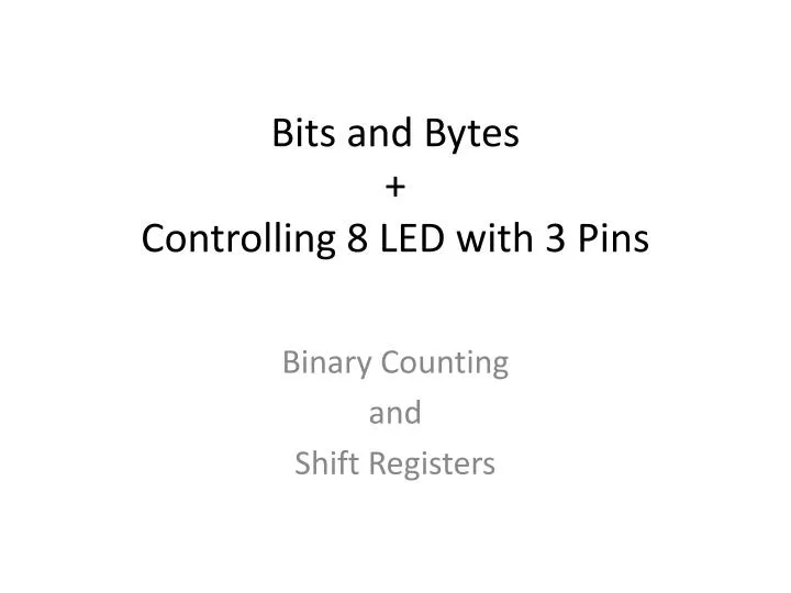
Bits and Bytes + Controlling 8 LED with 3 Pins. Binary Counting and Shift Registers . Decimal vs Binary.

E N D
Bits and Bytes+Controlling 8 LED with 3 Pins Binary Counting and Shift Registers
Decimal vs Binary In our everyday lives we use a base 10 systems. Every time we get to 10, we start counting again and basically we add all the “clumps” of 10 and anything less than 10, to designate a value so for instances the number, 11 = 10+1 or the number, 157 = 10 +10+10+10+10+10+10+10+10+10+10+10+10+10+10 + 7.
In a computer, we use a base 2 or binary system. Every time we get to 2, we start counting again and like with the decimal system, we add all the“clumps” of 2 and anything less than 10, to designate a value. Electrical signals can be high or low, on or off and binary with its number of 0 and 1, can easily be translated so a set of instructions can be transmitted to the various circuits of a computer.
Data and values are stored in bytes. A bit is a single part of a byte.
A byte is made of up 8 individual bits.A byte is the unit most computers use to represent a character such as a letter, number, or typographic symbol (for example, "g", "5", or "?"). A byte can also hold a string of bits that need to be used in some larger unit for application purposes (for example, the stream of bits that constitute a visual image for a program that displays images or the string of bits that constitutes the machine code of a computer program). In some computer systems, four bytes constitute a word, a unit that a computer processor can be designed to handle efficiently as it reads and processes each instruction
By combining the bits in a byte and turning ones on or off, we can represent in a byte any number between 0 and 255.
By using multiple bytes or bits we can represent ever larger numbers.
SHIFT REGISTERS Binary is the basis of how a microcontroller such as an communicates with its devices. Think about the Blink program and how it sends HIGH and LOW to turn an LED on and off. What if you ran out of inputs and outputs on the Arduino or want to use the I/O to control peripherals more Arduino’s 13 digital and 6 analog I/Os. You can use a chip called a shift register. The one we are using today is called the 74HC595, allows you to control 8 LEDs using only 3 pins on the Arduino. The 74HC595 is an 8 bit shit register meaning that it can receive 8 bits of information or a series of 8 0s and 1s that can be turned on or off. The 74HC595 is a series to parallel shift register meaning that is takes in a stream of 8 0s and 1s and then sends each values to one of the pins on the shift register. Let’s take a look at one and then understand how it works.
The pins are numbered counterclockwise starting from the upper left. The top of the chip usually has a notch in it. Q0-Q7 are where each of the 8 bits of data are distributed. A stream of 8 zeros and ones comes into the chip as a group and then each zero or one is shunted to one of The Q pins—serial input, parallel output. And in the case of lighting an LED, each one of 8 can be controlled with the incoming 0 or 1. The process is initiated by the SH_CP, pin 11, or the shift register clock pin which pulse a signal. Simultaneously, the data is sent by pin 15, DS, or Serial data input. Each pulse of the clock denotes the beginning and the end of a bit. After 8 bits of data have been sent and “collected”, the latch pin or pin 12, the storage register clock pin, releases all 8 bits to populated Q0-Q7.
How this all works is through something called "synchronous serial communication," i.e. you can pulse one pin up and down thereby communicating a data byte to the register bit by bit. It's by pulsing second pin, the clock pin, that you delineate between bits. This is in contrast to using the "asynchronous serial communication" of the Serial.begin() function which relies on the sender and the receiver to be set independently to an agreed upon specified data rate. Once the whole byte is transmitted to the register the HIGH or LOW messages held in each bit get parceled out to each of the individual output pins. This is the "parallel output" part, having all the pins do what you want them to do all at once. Channel 2 is the clock. Channel 1 is the data. Channel 0 is the latch.
VCC is connected to 3.3 V as is pin 10, Master Reclear, Active Low. Pin 13 or OE or Output enable, active low and pin 8, GND goes to Ground. Pin 9 or Q7 (Serial Out) is not connected Because we are not sending anything out in this Case.