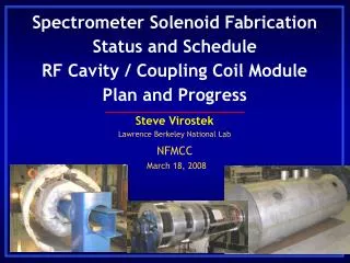
Download
1 / 21
210 likes | 279 Views
Other RF Cavity Components Mechanical Design and Analysis. RFCC Module Preliminary Design Review June 4, 2008. Allan DeMello Lawrence Berkeley National Lab. Other Module Components. Cavity Suspension. Dynamic Tuners. RF Coupler. Beryllium Window. Vacuum System.

E N D
Other RF Cavity Components Mechanical Design and Analysis RFCC Module Preliminary Design Review June 4, 2008 Allan DeMello Lawrence Berkeley National Lab
Other Module Components Cavity Suspension Dynamic Tuners RF Coupler Beryllium Window Vacuum System MICE RF and Coupling Coil Module PDR – Other RF Cavity Component Mechanical Design and Analysis Allan DeMello - Lawrence Berkeley National Lab - June 4, 2008 Allan DeMello - Lawrence Berkeley National Lab - June 4, 2008 Page 2
201 MHz Beryllium Windows 42 cm MICE RF and Coupling Coil Module PDR – Other RF Cavity Component Mechanical Design and Analysis Each cavity will require a pair of 0.38 mm thick pre-curved beryllium windows with TiN coating Double-curved shape, developed at Oxford, prevents buckling caused by thermal expansion due to RF heating Thermally induced deflections are predictable A die is applied at high temperature to form window Copper frames are brazed to beryllium windows in a subsequent process The window frame has been redesigned, in cooperation with the vendor, to increase the quality of the braze joint Allan DeMello - Lawrence Berkeley National Lab - June 4, 2008 Allan DeMello - Lawrence Berkeley National Lab - June 4, 2008 Page 3
Four Cavity Layout in Vacuum Vessel • Clocking of tuner position between adjacent cavities avoids interference • Actuators offset from cavity center plane due to width of coupling coil • Soft connection only (bellows) between tuner/actuators and vacuum vessel shell MICE RF and Coupling Coil Module PDR – Other RF Cavity Component Mechanical Design and Analysis Allan DeMello - Lawrence Berkeley National Lab - June 4, 2008 Allan DeMello - Lawrence Berkeley National Lab - June 4, 2008 Page 4
Cavity End View with Tuners • Six tuners per cavity provide individual frequency adjustment • Tuning automatically achieved through a feedback loop MICE RF and Coupling Coil Module PDR – Other RF Cavity Component Mechanical Design and Analysis Allan DeMello - Lawrence Berkeley National Lab - June 4, 2008 Allan DeMello - Lawrence Berkeley National Lab - June 4, 2008 Page 5
Cavity Tuner Design Features • Tuners are spaced evenly every 60º around cavity • Layout is offset by 15º from vertical to avoid conflict with cavity ports • Tuners touch cavity and apply loads only at the stiffener rings • Tuners operate in “push” mode only (i.e. squeezing) MICE RF and Coupling Coil Module PDR – Other RF Cavity Component Mechanical Design and Analysis Allan DeMello - Lawrence Berkeley National Lab - June 4, 2008 Allan DeMello - Lawrence Berkeley National Lab - June 4, 2008 Page 6
Tuner component Details Actuator & bellows assembly Fixed arm Pivoting arm Forces are transmitted to the stiffener ring by means of “push” loads applied to the tuner lever arms by the actuator assembly MICE RF and Coupling Coil Module PDR – Other RF Cavity Component Mechanical Design and Analysis Allan DeMello - Lawrence Berkeley National Lab - June 4, 2008 Allan DeMello - Lawrence Berkeley National Lab - June 4, 2008 Page 7
Cavity Tuner Section View Tuner actuator (likely nitrogen) Pivot point Dual bellows feedthrough Fixed (bolted) connection Ball contact only MICE RF and Coupling Coil Module PDR – Other RF Cavity Component Mechanical Design and Analysis Allan DeMello - Lawrence Berkeley National Lab - June 4, 2008 Allan DeMello - Lawrence Berkeley National Lab - June 4, 2008 Page 8
Cavity Tuning Parameters • The following parameters are based on a finite element analysis of the cavity shell. Tuning range is limited by material yield stress. • Overall cavity stiffness: 6120 N/mm • Tuning sensitivity: +230 kHz/mm per side • Tuning range: 0 to -460 kHz (0 to -2 mm per side) • Number of tuners: 6 • Maximum ring load/tuner: 4.1 kN • Max actuator press. (50 mm): 1.6 MPa (230 psi) MICE RF and Coupling Coil Module PDR – Other RF Cavity Component Mechanical Design and Analysis Allan DeMello - Lawrence Berkeley National Lab - June 4, 2008 Allan DeMello - Lawrence Berkeley National Lab - June 4, 2008 Page 9
Cavity Suspension System (option one) • Orthogonal six strut system provides kinematic cavity support • Orthogonal layout of struts allows accurate cavity alignment and positioning • Kinematic mounts prevent high cavity stresses caused by thermal distortion and over-constraint MICE RF and Coupling Coil Module PDR – Other RF Cavity Component Mechanical Design and Analysis Allan DeMello - Lawrence Berkeley National Lab - June 4, 2008 Allan DeMello - Lawrence Berkeley National Lab - June 4, 2008 Page 10
Cavity Suspension System 1 vertical strut 3 axial struts 2 horizontal struts MICE RF and Coupling Coil Module PDR – Other RF Cavity Component Mechanical Design and Analysis Allan DeMello - Lawrence Berkeley National Lab - June 4, 2008 Allan DeMello - Lawrence Berkeley National Lab - June 4, 2008 Page 11
Strut End Connection Details The cavity end of the vertical and one of the horizontal struts are attached directly to the stiffener ring The cavity end of the axial and one of the horizontal struts are attached to the fixed leg of a tuner One end of the struts is attached to a fixed lug welded to the ID of the vacuum vessel MICE RF and Coupling Coil Module PDR – Other RF Cavity Component Mechanical Design and Analysis Allan DeMello - Lawrence Berkeley National Lab - June 4, 2008 Allan DeMello - Lawrence Berkeley National Lab - June 4, 2008 Page 12
Four Cavity Layout in Vacuum Vessel • Each cavity contains a dedicated set of suspension struts • No contact between pairs of close packed cavities • Struts designed to axially fix outside end of cavity pairs • Tuning deflections increase cavity gap MICE RF and Coupling Coil Module PDR – Other RF Cavity Component Mechanical Design and Analysis Allan DeMello - Lawrence Berkeley National Lab - June 4, 2008 Allan DeMello - Lawrence Berkeley National Lab - June 4, 2008 Page 13
Hexapod Strut Arrangement (option two) • Analysis of a hexapod strut system is ongoing • Each cavity would contain a dedicated set of 6 suspension struts arranged in a hexapod type formation • This system spreads the gravity load of the cavity across several struts Example of a hexapod stage MICE RF and Coupling Coil Module PDR – Other RF Cavity Component Mechanical Design and Analysis Allan DeMello - Lawrence Berkeley National Lab - June 4, 2008 Allan DeMello - Lawrence Berkeley National Lab - June 4, 2008 Page 14
Hexapod Strut Cavity Mounting • Copper mounting block would be e-beam welded directly to the RF cavity • The cavity has very little deformation at mounting block location MICE RF and Coupling Coil Module PDR – Other RF Cavity Component Mechanical Design and Analysis Allan DeMello - Lawrence Berkeley National Lab - June 4, 2008 Allan DeMello - Lawrence Berkeley National Lab - June 4, 2008 Page 15
Hexapod Strut Mounting to Vessel Copper strut mounts e-beam welded to the outside of the cavity Stainless steel strut mounts welded to the inside of the vacuum vessel MICE RF and Coupling Coil Module PDR – Other RF Cavity Component Mechanical Design and Analysis Allan DeMello - Lawrence Berkeley National Lab - June 4, 2008 Allan DeMello - Lawrence Berkeley National Lab - June 4, 2008 Page 16
Cavity RF Coupler Window MICE RF and Coupling Coil Module PDR – Other RF Cavity Component Mechanical Design and Analysis Coupler design incorporates SNS style RF windows manufactured by Toshiba (off the shelf) MICE will require a bellows connection between the window and the coupler Allan DeMello - Lawrence Berkeley National Lab - June 4, 2008 Allan DeMello - Lawrence Berkeley National Lab - June 4, 2008 Page 17
Prototype Cavity RF Couplers MICE RF and Coupling Coil Module PDR – Other RF Cavity Component Mechanical Design and Analysis Coupling loops are fabricated using standard copper co-ax Parts to be joined by e-beam welding (where possible) and torch brazing Coupling loop has integrated cooling Allan DeMello - Lawrence Berkeley National Lab - June 4, 2008 Allan DeMello - Lawrence Berkeley National Lab - June 4, 2008 Page 18
MICE Cavity RF Couplers • A bellows connection between the coupler and the vacuum vessel provides compliance for mating with the cavity • Design incorporates a simple flange for RF sealing between RF coupler and the cavity MICE RF and Coupling Coil Module PDR – Other RF Cavity Component Mechanical Design and Analysis Allan DeMello - Lawrence Berkeley National Lab - June 4, 2008 Allan DeMello - Lawrence Berkeley National Lab - June 4, 2008 Page 19
Vacuum System NEG (non-evaporable getter) pump Cross sectional view of vacuum system • A NEG pump has been chosen because it will be unaffected by the large magnetic field • A vacuum path between the inside and outside of the cavity eliminates the risk of high pressure differentials and the possible rupture of the thin beryllium window MICE RF and Coupling Coil Module PDR – Other RF Cavity Component Mechanical Design and Analysis Allan DeMello - Lawrence Berkeley National Lab - June 4, 2008 Allan DeMello - Lawrence Berkeley National Lab - June 4, 2008 Page 20
Other Module Summary • Beryllium window design is complete and the windows are ready to be ordered (8 per module needed) • Conceptual design of the cavity frequency tuners is complete (analysis will need to be performed) • Two different cavity suspension systems are currently being investigated – orthogonal and hexapod • The RF coupler will be based on the SNS design using the off the shelf Toshiba RF window • The vacuum system includes an annular feature coupling the inside and the outside of the cavity (further analysis of vacuum rupture scenario needs to be done) Allan DeMello - Lawrence Berkeley National Lab - June 4, 2008