Download
1 / 10
130 likes | 262 Views
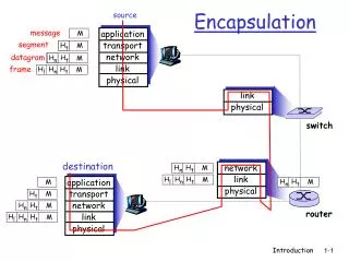
Ethernet encapsulation. The Preamble (7 bytes) and Start Frame Delimiter (SFD) (1 byte) fields are used for synchronization between the sending and receiving devices. The Destination MAC Address field (6 bytes) is the identifier for the intended recipient Source MAC Address Field

E N D
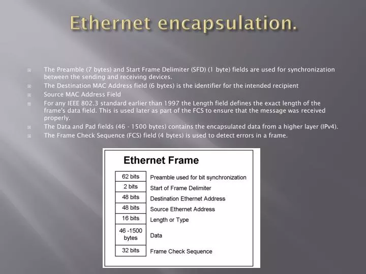
Ethernet encapsulation. • The Preamble (7 bytes) and Start Frame Delimiter (SFD) (1 byte) fields are used for synchronization between the sending and receiving devices. • The Destination MAC Address field (6 bytes) is the identifier for the intended recipient • Source MAC Address Field • For any IEEE 802.3 standard earlier than 1997 the Length field defines the exact length of the frame's data field. This is used later as part of the FCS to ensure that the message was received properly. • The Data and Pad fields (46 - 1500 bytes) contains the encapsulated data from a higher layer (IPv4). • The Frame Check Sequence (FCS) field (4 bytes) is used to detect errors in a frame.
The Ethernet MAC Address and Network Addressing • The MAC Address - A unique identifier called a Media Access Control (MAC) address was created to assist in determining the source and destination address within an Ethernet network. An Ethernet MAC address is a 48-bit binary value expressed as 12 hexadecimal digits. • The MAC address is used by the NIC to determine if a message should be passed to the upper layers for processing. . If there is no match, the device discards the frame. When the frame reaches the destination where the MAC of the NIC matches the destination MAC of the frame, the NIC passes the frame up the OSI layers, where the decapsulation process take place. • OSI Data Link layer (Layer 2) physical addressing, implemented as an Ethernet MAC address, is used to transport the frame across the local media. Only locally significant. • Network layer (Layer 3) addresses, such as IPv4 addresses, provide the ubiquitous, logical addressing that is understood at both source and destination. To arrive at its eventual destination, a packet carries the destination Layer 3 address from its source. However, as it is framed by the different Data Link layer protocols along the way, the Layer 2 address it receives each time applies only to that local portion of the journey and its media.
Unicasts, Broadcasts, Multicasts • A unicast MAC address is the unique address used when a frame is sent from a single transmitting device to single destination device. • With a broadcast, the packet contains a destination IP address that has all ones (1s) in the host portion. This numbering in the address means that all hosts on that local network (broadcast domain) will receive and process the packet. Many network protocols, such as Dynamic Host Configuration Protocol (DHCP) and Address Resolution Protocol (ARP), use broadcasts • Multicast addresses allow a source device to send a packet to a group of devices. Devices that belong to a multicast group are assigned a multicast group IP address. The range of multicast addresses is from 224.0.0.0 to 239.255.255.255. Because multicast addresses represent a group of addresses (sometimes called a host group), they can only be used as the destination of a packet. The source will always have a unicast address.
Media Access Control, Collisions • In a shared media environment, all devices have guaranteed access to the medium, but they have no prioritized claim on it. • In the CSMA/CD access method, all network devices that have messages to send must listen before transmitting. If a device detects a signal from another device, it will wait for a specified amount of time before attempting to transmit. • If the distance between devices is such that the latency of one device's signals means that signals are not detected by a second device, the second device may start to transmit, too. • Listening mode - can detect when a collision occurs on the shared media. The detection of a collision is made possible because all devices can detect an increase in the amplitude of the signal above the normal level.
Hubs and Collision Domains • Causes for collisions when using Hubs – • More devices are being connected to the network. • Devices access the network media more frequently. • Distances between devices are increasing. • Hubs and repeaters are intermediary devices that extend the distance that Ethernet cables can reach. Because hubs operate at the Physical layer, dealing only with the signals on the media, collisions can occur between the devices they connect and within the hubs themselves. • Although CSMA/CD is a frame collision management system, it was designed to manage collisions for only limited numbers of devices and on networks with light network usage. • Invention of switches – the complete solution for the collision problem.
Ethernet Timing • Latency - The electrical signal that is transmitted takes a certain amount of time (latency) to propagate (travel) down the cable. Each hub or repeater in the signal's path adds latency as it forwards the bits from one port to the next. This accumulated delay increases the likelihood that collisions will occur because a listening node may transition into transmitting signals while the hub or repeater is processing the message. • In half-duplex mode, if a collision has not occurred, the sending device will transmit 64 bits of timing synchronization information, which is known as the Preamble. • For each different media speed, a period of time is required for a bit to be placed and sensed on the media. This period of time is referred to as the bit time. On 10-Mbps Ethernet, one bit at the MAC layer requires 100 nanoseconds (nS) to transmit. At 100 Mbps, that same bit requires 10 nS to transmit. • For all speeds of Ethernet transmission at or below 1000 Mbps, the standard describes how an individual transmission may be no smaller than the slot time. Slot time for 10- and 100-Mbps Ethernet is 512 bit times, or 64 octets. Slot time for 1000-Mbps Ethernet is 4096 bit times, or 512 octets. • The Ethernet standards require a minimum spacing between two non-colliding frames. This gives the media time to stabilize after the transmission of the previous frame and time for the devices to process the frame. Referred to as the interframe spacing, this time is measured from the last bit of the FCS field of one frame to the first bit of the Preamble of the next frame. • Jam Signal and Backoff Timing
IEEE 802.3, 10, 100 and 1000 megabit Ethernet • The principal 10 Mbps implementations of Ethernet include: • 10BASE5 using Thicknet coaxial cable • 10BASE2 using Thinnet coaxial cable • 10BASE-T using Cat3/Cat5 unshielded twisted-pair cable • 100 Mbps - Fast Ethernet • 100BASE-TX using Cat5 or later UTP – electrical signals. • 100BASE-FX using fiber-optic cable – light impulses. • 1000 Mbps - Gigabit Ethernet - The development of Gigabit Ethernet standards resulted in specifications for UTP copper, single-mode fiber, and multimode fiber. • 1000BASE-T Ethernet - 1000BASE-T Ethernet provides full-duplex transmission using all four pairs in Category 5 or later UTP cable. Gigabit Ethernet over copper wire enables an increase from 100 Mbps per wire pair to 125 Mbps per wire pair, or 500 Mbps for the four pairs. Each wire pair signals in full duplex, doubling the 500 Mbps to 1000 Mbps. • 1000BASE-SX and 1000BASE-LX Ethernet Using Fiber-Optics - The fiber versions of Gigabit Ethernet - 1000BASE-SX and 1000BASE-LX - offer the following advantages over UTP: noise immunity, small physical size, and increased unrepeated distances and bandwidth.
Using Switches in Ethernet and comparison to Hubs • Some of the major issues with hubs are : • Scalability • Latency • Network Failure • Collisions • Advantages of switches over hubs: • Nodes are Connected Directly • Dedicated bandwidth to each port - Each node has the full media bandwidth available in the connection between the node and the switch. • Collision-free environment - A dedicated point-to-point connection to a switch also removes any media contention between devices, allowing a node to operate with few or no collisions • Full-duplex operation - Switching also allows a network to operate as a full-duplex Ethernet environment.
Switches • Ethernet switches selectively forward individual frames from a receiving port to the port where the destination node is connected. • Forwarding is Based on the Destination MAC - The switch maintains a table, called a MAC table. that matches a destination MAC address with the port used to connect to a node. For each incoming frame, the destination MAC address in the frame header is compared to the list of addresses in the MAC table. If a match is found, the port number in the table that is paired with the MAC address is used as the exit port for the frame. • Switch Operation • To accomplish their purpose, Ethernet LAN switches use five basic operations: • Learning - The MAC table must be populated with MAC addresses and their corresponding ports. • Aging - The entries in the MAC table acquired by the Learning process are time stamped. • Flooding - If the switch does not know to which port to send a frame because the destination MAC address is not in the MAC table, the switch sends the frame to all ports except the port on which the frame arrived. • Selective Forwarding - Selective forwarding is the process of examining a frame's destination MAC address and forwarding it out the appropriate port. • Filtering - In some cases, a frame is not forwarded. This process is called frame filtering.
ARP – Address Resolution Protocol • The ARP protocol provides two basic functions: • Resolving IPv4 addresses to MAC addresses – The switch maps an IPv4 address to a MAC address from a table in it’s RAM called ARP table. • Maintaining the ARP Table - The ARP table is maintained dynamically. There are two ways that a device can gather MAC addresses. One way is to monitor the traffic that occurs on the local network segment. Another way a device can get an address pair is to broadcast an ARP request. • Proxy ARP - There are circumstances under which a host might send an ARP request seeking to map an IPv4 address outside of the range of the local network. In these cases, the device sends ARP requests for IPv4 addresses not on the local network instead of requesting the MAC address associated with the IPv4 address of the gateway. To provide a MAC address for these hosts, a router interface may use a proxy ARP to respond on behalf of these remote hosts. • Overhead on the Media – as ARP is broadcasted, it creates overhead on the media. Only a problem in very large networks. • Security - In some cases, the use of ARP can lead to a potential security risk. ARP spoofing, or ARP poisoning, is a technique used by an attacker to inject the wrong MAC address association into a network by issuing fake ARP requests.