Download
1 / 22
230 likes | 442 Views
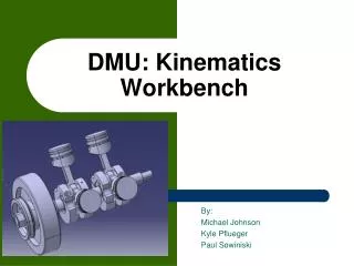
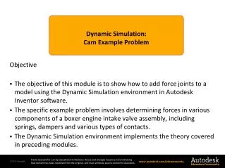
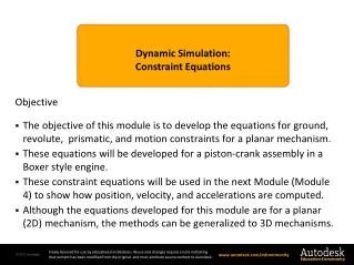
Dynamic Simulation : Piston Assembly Example . Objective The objective of this module is to show how an example problem is solved using the Dynamic Simulation environment within Autodesk Inventor software.

E N D
Dynamic Simulation: • Piston Assembly Example Objective • Theobjective of this module is to show how an example problem is solved using the Dynamic Simulation environment within Autodesk Inventor software. • This kinematic analysis problem involves imposing a rotational motion on the rotating assembly of a boxer style engine. • The Output Grapher is used to plot computed moments, displacements, velocities, and accelerations. • Friction in a prismatic joint is also illustrated.
Components Section 4 – Dynamic Simulation Module 5 - Piston Assembly Example Page 2 Crank Shaft Pistons x 4 Cylinder Liner x 4 Crankshaft Bearings x 3 Connecting rods and piston pin bearing assemblies x 4
Sub-assemblies Section 4 – Dynamic Simulation Module 5 - Piston Assembly Example Page 3 • The connecting rod components and the piston components were modeled as sub-assemblies. • This will cause Inventor and Dynamic Simulation to treat them as rigid bodies with no relative motion between the sub-assembly parts. Piston Assembly Connecting Rod Assembly
Assembly ConstraintsGround Joints Section 4 – Dynamic Simulation Module 5 - Piston Assembly Example Page 4 The cylinder liners and crankshaft bearings are fixed in the engine block and cannot move. They were positioned using the cylinder block and then grounded in Inventor. The ground is carried over into Dynamic Simulation.
Assembly ConstraintsRevolute Joint Section 4 – Dynamic Simulation Module 5 - Piston Assembly Example Page 5 A mate is placed between the centerline of the crankshaft and the centerline of the crankshaft bearing. This constraint will be converted to a revolute joint in Dynamic Simulation.
Assembly ConstraintsAxial Crankshaft Constraint Section 4 – Dynamic Simulation Module 5 - Piston Assembly Example Page 6 • A mate is placed between the two surfaces shown to position the crankshaft along the axis of the engine. • This constraint removes the translation DOF between the crankshaft and bearings. • A 2mm offset is required.
Assembly ConstraintsRevolute Joints Section 4 – Dynamic Simulation Module 5 - Piston Assembly Example Page 7 Mates are placed between the centerlines of the piston bearings and the crankshaft journals. These will automatically be converted to revolute joints by Dynamic Simulation. Crankshaft Journals
Assembly ConstraintsAxial Constraint Section 4 – Dynamic Simulation Module 5 - Piston Assembly Example Page 8 • A mate is placed between the machined connecting rod surface and the face of the crankshaft journal. • This removes the translational DOF between the connecting rod assembly and the crankshaft. • This constraint is applied to each connecting rod assembly. Machined connecting rod surface Crankshaft journal face
Assembly ConstraintsRevolute Joints Section 4 – Dynamic Simulation Module 5 - Piston Assembly Example Page 9 In a manner similar to the other revolute joints, centerline mates are placed between the pistons and the connecting rod assemblies. This is called “Joint 1” in Module 3.
Assembly ConstraintsPrismatic Joints Section 4 – Dynamic Simulation Module 5 - Piston Assembly Example Page 10 The final set of constraints is between the cylinder liners and the pistons. Centerline mates are again used. The centerline constraints will allow translational motion of the piston along the axis of the cylinder liner.
Completed Assembly Section 4 – Dynamic Simulation Module 5 - Piston Assembly Example Page 11 The complete assembly is shown in the figure. The crankshaft can be rotated and all other parts move in accordance to the assembly constraints.
Dynamic Simulation Environment Section 4 – Dynamic Simulation Module 5 - Piston Assembly Example Page 12
Dynamic Simulation Environment Section 4 – Dynamic Simulation Module 5 - Piston Assembly Example Page 13 3 Grounded Crank Bearings (one bearing has two parts) 4 Grounded Cylinder Liners Crankshaft 4 Piston Assemblies 4 Connecting Rod Assemblies Kinematic constraints are automatically generated by Dynamic Simulation from the assembly constraints.
Mobility Section 4 – Dynamic Simulation Module 5 - Piston Assembly Example Page 14 • The mobility of the mechanism is checked using the Mechanism Status feature on the ribbon. • The mechanism has a mobility of one as expected. • The free DOF is the rotational DOF of the crankshaft.
Motion Groups Section 4 – Dynamic Simulation Module 5 - Piston Assembly Example Page 15 The parts that can move are shown in a solid color. The parts that cannot move are shown in transparent mode.
Motion Constraint Section 4 – Dynamic Simulation Module 5 - Piston Assembly Example Page 16 • A mobility of one requires that one motion constraint be specified. • A rotational velocity of 3600 deg/sec is applied to the crankshaft rotational degree of freedom. • This is equivalent to 600 rpm. Right click on properties for Revolution Joint 1
Input Motion Section 4 – Dynamic Simulation Module 5 - Piston Assembly Example Page 17 As a check, the computed angular velocity is constant and is 3,600 deg/sec which agrees with the input angular velocity. Velocity Position Acceleration The angular position of the crank shaft should be a linear function of time with a slope of 3,600 deg/sec. The computed position is correct. The angular acceleration of the crank shaft should be zero since the velocity is a constant. The computed acceleration is correct.
Input Torque Section 4 – Dynamic Simulation Module 5 - Piston Assembly Example Page 18 The computed torque that is required to impose a constant angular velocity of 3,600 deg/sec on the crankshaft is shown in the Output Grapher plot. Notice that the input torque is sinusoidal.
Input Torque Section 4 – Dynamic Simulation Module 5 - Piston Assembly Example Page 19 • Positive values of the torque mean that energy is being put into the system so that the constant crankshaft angular velocity is maintained. • Negative values of the torque mean that energy is being taken out of the system so that the constant crankshaft angular velocity is maintained. • Since there is no friction in the system the net energy required to maintain a constant angular velocity of the crankshaft is zero. • The average torque is zero which indicates that the average input power is zero.
Friction Section 4 – Dynamic Simulation Module 5 - Piston Assembly Example Page 20 Friction can be added by editing the properties of a joint. In this case we are adding a coefficient of friction of 0.2 to the translational degree of freedom of the prismatic joint between the piston and cylinder liner. Friction is added to all joints using this approach. The properties dialog box is obtained by right clicking on the joint.
Input Torque with Friction Section 4 – Dynamic Simulation Module 5 - Piston Assembly Example Page 21 The addition of a coefficient of friction of 0.2 increased the average torque from zero to 491 Nm. The input power required to overcome the friction in the system is Max = 6,267 Nm Average = 491 Nm Min = -5,776 Nm
Module Summary Section 4 – Dynamic Simulation Module 5 - Piston Assembly Example Page 22 • This module provided an example of how to perform a dynamic simulation of a mechanism using Autodesk Inventor’s Dynamic Simulation environment. • This kinematic analysis problem involved imposing a rotational motion on the rotating assembly of a boxer style engine. • Correlations were made between the theory presented in previous modules and this example. • Although the mathematics is hidden from the user, the input information associated with joints and constraints can clearly be seen in the user interface.