Download
1 / 13
130 likes | 213 Views
Hierarchical Control Notes – Blending Style. Follows quad example Note: coil drivers and ESD are LASTI style; seismic noise is outdated. Longitudinal Hierarchical Architecture . Longitudinal Hierarchical Architecture . Low Pass = “LP” High Pass = “HP”. Complimentary Blend Filter Design.

E N D
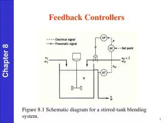
Hierarchical Control Notes – Blending Style Follows quad example Note: coil drivers and ESD are LASTI style; seismic noise is outdated
Longitudinal Hierarchical Architecture Low Pass = “LP” High Pass = “HP”
Complimentary Blend Filter Design • Blend Design Process: • Chose blend frequencies based on actuator range cross overs • The high pass filters are generated as compliments of the low pass filters, so only low pass filter design is needed • Start building blends from UIM Low Pass (LPU->P) • Work your way through the filters down to TST Low Pass (HPP->T)
Complimentary Blend Filter Design • Our first attempt at the design: • The UIM Low Pass (LPU->P)is just a complex pair of poles at UIM / PUM crossover (@ 8 Hz, 60 deg phase) • The PUM High Pass (HPU->P) is the compliment of the UIM Low Pass • The PUM Low Pass (LPP->T) is a pair of complex poles at the PUM / TST crossover (@ 15 Hz, 60 deg phase) • The TST High Pass (HPP->T) is the compliment of the PUM Low Pass
Complimentary Blend Filter Design • TOTAL sums to one • Gain peaking is no more than 2 • PUM “band pass” comes up as f^2, false as 1/f^2 • TST High Pass comes up as f^4
Plant Inversion Filter Design • Complimentary blending/distribution only works if paths are in the same units in the region where the signals are blended • As discussed in G1200632, ISC desires that “from the outside” the transfer function looks as TST Drive > TST Displacment transfer function • So, must invert the *ratio* of dynamics between [UIM or PUM] Drive > TST disp and TST Drive > TST disp • For starters, we use a simplified version of the model that ignores the complicated resonant dynamics (“fit” by hand, and scaled to match the State Space model) • We do include a high-frequency roll-off so gain of inversion filter does not go to infinity High frequency roll-up to truncate gain Complicated dynamics are ignored
Plant Inversion Filter Design UIM Example HF Cut-Off Total Plant Inversion Filter is ratio: TST>TST / UIM > TST f^6 f^-2 f^4 Scaled to SS model flat at DC f^-2 Frequency (Hz)
Plant Inversion Filter Design The same in the region of blending