Download
1 / 18
180 likes | 298 Views
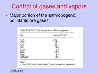
Dynamic vacuum - Collimator technology for suppression and control of desorption gases. Workshop on Materials for Collimators and Beam Absorbers, CERN September 04 th 2007 C. Omet, FAIR Synchrotrons. Contents. Introduction Primary loss mechanisms Collimator placement Absorber surface

E N D
Dynamic vacuum - Collimator technology for suppression and control of desorption gases Workshop on Materials for Collimators and Beam Absorbers, CERN September 04th 2007 C. Omet, FAIR Synchrotrons
Contents • Introduction • Primary loss mechanisms • Collimator placement • Absorber surface • Collimator system design • Measurements and simulations of beam life time • Outlook C. Omet
Introduction • Observation of fast, intensity dependant beam losses during operation with low charge state high intensity heavy ion beams in our synchrotron SIS18 (well below space charge limit). • A large residual gas pressure rise was observed the same time. • Losses depend on: • injected beam intensity • injection losses • RF capture losses • residual gas pressure • 1/energy (1st approx.) C. Omet
Primary loss mechanism • A beam ion hits residual gas atoms/molecules and loses one or more electron(s) • This ion is lost after the next dipole by different magnetic rigidity (dp/p q0/q - 1, e.g. for U28+U29+dp/p = -3.45% !) • There, a shower of secondary particles is produced by ion stimulated desorption with a rate of 104 mol/ion. • An avalanche process can be initiated! There are more loss processes, but this one can be controlled with collimators / catchers! C. Omet
Collimator placement in SIS18 without collimators with collimators loss intensity • SIS 18, section S02 • E = 11.4 MeV/u • U28+ U29+ • 2,500,000 particles • Lattice is fixed • Collimator position is ‘forced’ by dipole position horizontal vertical C. Omet
Collimator placement in SIS18 • Transversally: • Do not reduce acceptance of the machine! • Maximise collimation efficiency for reference ion (U28+) • Have to make a compromise always in existing machines! • Hints for optimal placement and lattice design: see presentation of P. Spiller / J. Stadlmann for details (example of SIS100 lattice) Calculated for only 10 installed collimators, two sections cannot be used because of non-moveable insertions (extraction septum and ion cooler). C. Omet
StrahlSim Code • Vacuum calculations • Static • p0, Seff, vacuum conductance,NEG coatings, cryogenic surfaces,residual gas components • Dynamic (source of beam losses) • Synchrotron cycle • Seff,cold(p, T): analytical model • Systematic losses (injection, RF capture) • Projectile ionisation spi(E, Dq) from Shevelko, Olson, collaboration with AP • Coulomb scattering • Target ionisation • Ion stimulated desorption (desorption rate scaled with (dE/dx)2) couples losses to residual gas pressure rise • Linear ion optics • Loss distribution, catching efficiency • Reads and writes many formats (AML, MIRKO, MAD-X, WinAGILE) • Benchmarked with many machine experiments C. Omet
Charge-exchange process • Projectile-ionisationof the circulating beam by rest-gas particles • charge-exchange cross sections s(E, q, Dq) acc. to Olson or experimentally determined ~ 10-23...10-21 m² • single- and multiple ionisation possible • desorption rate h~ 2...3*104 (depends on angle and energy) collimation feasible C. Omet
Dynamic Vacuum • Loss rate of the beam • Production rate of ionised residual gas • Dynamic vacuum (here shown without collimators) • Numeric integration, turn by turn C. Omet
Scaling of the desorption rate • Experimental hints:Desorption rate scales with (dE/dx)² of the incident ion. • A. Molvik, Electrons and gas versus high brightness ion beams, 25th International Workshop on Physics of High Energy Density in Matter • M. Bender et al, Energy-Loss Dependence of the Ion-Induced Desorption Yield Measured with Ar10+ Ions at GSI-HHT • Implementation: • Calculate dE/dx with ATIMA and rescale desorption rate. C. Omet
Time dependent particle number • August 2007 (last week) • Ramp rate of 4 T/s • Closed orbit corrected • Enhanced pumping speed • NEG coating of one dipole and three quadrupole chambers • Fired Ti-sub pumps December 2003 No ramping, 7.1 MeV/u C. Omet
Beam absorber: Geometry • Material choice: • Has to stop heavy ions at energies up to 200 MeV/u 238U28+ range is ~ 1.5 mm • Should have a low desorption rate at the active surface • Use ion range calculations (ATIMA) and desorption measurements together with surface characterisation by ERDA • Result: • Cu core • Coated with a few 100 nm Au • Desorption rate is not 0! • In prototypes: Two shapes • Block better for desorption • Wedge better for pumping (desorption gases cos-distributed) 20 cm 5 cm C. Omet
Beam absorber: Surface • ERDA (Elastic Recoil Detection Analysis) measurements taken at the HLI in GSI (H. Kollmus / M. Bender) from Wednesday last week with 1.4 MeV/u 136Xe18+ (dE/dx similar to ~10 MeV/u 238U): • Au coated surface has lowest desorption rate (tested under perpendicular angle of incidence) • ~ 80 mol/ion • ~ 25 mol/ion after thermal treatment • pure Au, mechanically treated: 1200 mol/ion (!) • 300 nm Au • 200 nm Ni as a diffusion barrier C. Omet
Collimator system circulating beam • Control and confine desorption gases where they are produced • Absorber: Cu, Au coated • Secondary chamber • Need as much pumping speed as possible • NEG coating, wherever possible • Flanged Ti-sublimation and ion pumps (top mounted, not shown) • Lots of diagnostics • total and partial pressures • ion current of U29+ • temperature of absorber moveable C. Omet
Time dependant particle number • Ultimate goal for FAIR: accelerate 1.25*1011 U28+ particles from 11.4 to 200 MeV/u and inject 4 of them into SIS100 • Simulations using StrahlSim before and after SIS18 upgrade: • Enhanced ramp rate of 10 T/s • Reduced injection and RF capture losses • Enhanced pumping speed by NEG coating of all dipole and quadrupole chambers C. Omet
Conclusions • Dynamic vacuum problems • Caused by charge change process of low charged ions at low energies • Coupled to ion stimulated desorption • Can be partially solved by a suitable collimator system, UHV, injection and RF systems upgrade • Simulation model does exist • Including Coulomb scattering, target ionisation • Other beam losses remain during (esp. at high intensity operation) • Resonances, space charge • Closed orbit distortions • RF bucket size / energy mismatch from LINAC / pre-acc. • … C. Omet
Outlook • In preparation • Civil construction of two collimator prototypes finished • Installation into SIS18 during winter shutdown 2007 (section S02, S03) • Measurement campaign Jan/Feb 2008 with U28+ • If successful, 8 collimators will follow • Ongoing effort in GSI • Materials and desorption (ERDA) • Simulation codes • Measurements with Au at the AGS? • … StrahlSim publication: Charge change-induced beam losses under dynamic vacuum conditions in ring accelerators C Omet et al 2006 New J. Phys. 8 284 doi:10.1088/1367-2630/8/11/284 C. Omet
Questions? C. Omet