Download
1 / 37
370 likes | 462 Views
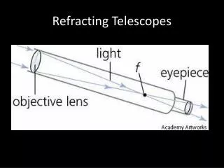
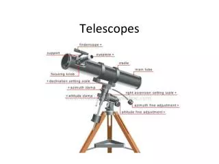
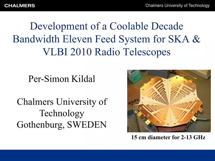
Development of a Coolable Decade Bandwidth Eleven Feed System for SKA & VLBI 2010 Radio Telescopes. Per-Simon Kildal Chalmers University of Technology Gothenburg, SWEDEN. 15 cm diameter for 2-13 GHz. Start in 2003: ATA array, forrunner of US SKA (500 MHz – 10 GHz).

E N D
Development of a Coolable Decade Bandwidth Eleven Feed System for SKA & VLBI 2010 Radio Telescopes Per-Simon Kildal Chalmers University of Technology Gothenburg, SWEDEN 15 cm diameter for 2-13 GHz
Start in 2003: ATA array, forrunner of US SKA (500 MHz – 10 GHz)
Size and complexity for fmin= 500 MHz Eleven feed: Eleven times smaller & No problem with phase center variations ATA feed: Too large & Problem with phase center variations
Size and complexity for fmin= 500 MHz Eleven feed: Eleven times smaller & No problem with phase center variations ATA feed: Too large & Problem with phase center variations
Idea behind Chalmers feed • Two parallel dipoles over ground • from book about Radio Telescopes by Christiansen and Högbom • equal E- and H-plane patterns • phase center is locked to the ground plane • low far-out sidelobes and backlobes. • Bandwidth by • Logperiodic • Folded dipoles • ”Eleven” name inspired by • Basic dual-dipole geometry • Directivity 10-11 dBi and S11 <-10 dB • Over more than decade bandwidth (>11) • And size eleven times smaller than classical log-periodic feeds
Interdisciplinary team developing coolable VLBI2010 hardware from Sept 2008 • Interdisciplinary research at Chalmers • Department of Signals and Systems, Chalmers • Department of Radio and Space Sciences, Chalmers • Department of Microtechnology and Nanoscience • Chalmers Industriteknik (CIT) for helping to commercialize: • No dedicated SKA funding since 2003-2005 (US SKA project) • Hardware orders from VLBI 2010 partners: • Vertex (BKG) in Germany • Statkart in Norway • Haystack radio telescope in USA
Main contributions • Dr Jian Yang: “Electrical design” • Dr Miroslav Pantaleev and Leif Helldner: “Mechanical and cryogenic design” • Benjamin Klein, South Africa “Noise modeling” • Drawing, assembled feed, cooled feed
The following choices were made during the project • All materials MUST stand cryogenic temp • 4 separate panels (petals) with log-per. dipoles • PCB technology for antenna petals • Minimize thickness of dielectric in center • 2x4 ports with no crossing lines in center puck • Differential feed line impedance 200 Ohms • Experimental model has 2x4 coaxial ports, transf to 50 Ohms • We work also with 4 differential 200 Ohms LNAs, 2 per polarization
Front and back sides of Eleven feed with 8 single-ended ports
Integration with differential 200 ohm LNAs from Caltech • Four cryogenic differential 200 ohm LNAs from Caltech mounted on the back side of the ground plane • Requires in addition two power combiners to get two polarizations out from the cryostat • Expected delivery of LNAs: June 2010
Early computed still valid efficiency vs. subtended half angle Optimum subtended angle >50 deg
Early computed figure of Merit versus F/Doptimum F/D = 0.4 (i.e. 64 deg) Useful range 0.33 < F/D < 0.50, i.e. 75 deg < q0 < 55 deg
Simulations and Measurements at Chalmersof input reflection coefficient (4 ports excited)(power dividers and cables were calibrated away)
Co- and crosspolar patterns in 45 deg planetotal and with removed higher order f variations
Co- and crosspolar patterns in 45 deg planetotal and with removed higher order f variations
Co- and crosspolar patterns in 45 deg planetotal and with removed higher order f variations
Co- and crosspolar patterns in 45 deg planetotal and with removed higher order f variations
Co- and crosspolar patterns in 45 deg planetotal and with removed higher order f variations
Co- and crosspolar patterns in 45 deg planetotal and with removed higher order f variations
Co- and crosspolar patterns in 45 deg planetotal and with removed higher order f variations
Co- and crosspolar patterns in 45 deg planetotal and with removed higher order f variations
Co- and crosspolar patterns in 45 deg planetotal and with removed higher order f variations
Co- and crosspolar patterns in 45 deg planetotal and with removed higher order f variations
Co- and crosspolar patterns in 45 deg planetotal and with removed higher order f variations
Co- and crosspolar patterns in 45 deg planetotal and with removed higher order f variations
Sub-efficiencies from measured radiation patterns at TUD Looks good, except for BOR1 efficiency below 2.5 GHz and above 9 GHz. BOR1 efficiency is power lost in sidelobes due to higher order f variations.
After survival test to 14 KThree stages of cryostat (Dewar) can be seen
Deformation simulations and testing at cryogenic temperatures
Integration of Eleven feed in cryostat The MIL infrared filter reduces the temperature to 25K The 70K shield has infrared window of one layer Teflon The temperature on the Feed surface is measured with temperature sensor Lakeshore DT-470 mounted on thin copper support soldered at the edge of the third dipole.
Front and back sides of Eleven feed with 8 single-ended ports
Noise temperatures Total predicted and measured Sky and ground LNA Ohmic loss
Summary of measurement results • Hardware: Good. Appears solid and appealing • Matching: abs(S11) < -10 dB up to 13 GHz • measured by removing effects of power dividers and cables by calibration • Independent gain measurements at Technical University of Denmark • Losses smaller than 0.5 dB (Uncertainty due to multiple reflections between 180 deg hybrid, 3dB power divider and antenna, which were not calibrated out in this case) • Radiation patterns: Good between 2.5 and 9 GHz. Otherwise low BOR1 efficiency • Overall efficiency in reflector better than -2 dB between 2.5 and 9 GHz • Promising system noise measurements with TLNA = 5 – 10 K
Integration with differential 200 ohm LNAs from Caltech • Four cryogenic differential 200 ohm LNAs from Caltech mounted on the back side of the ground plane • Requires in addition two power combiners to get two polarizations out from the cryostat • Expected delivery of LNAs: June 2010
Planned work • Design and test compact 1-10 GHz SKA model • Improve low BOR1 efficiency above 9 GHz • More studies of radiation fields and S11 in cryostat • Improve noise models • Test with 4 differential LNAs • Integrate and test with passive balun and 2 single-ended LNAs • More optimizatioins and compare with horn solutions (narrow band)
Comparison of figure of merit A/T (predicted) A/T of the Eleven feed system • For a reflector of 1 m2 areawith subtended half angle of 60o, i.e. F/D = 0.433. • Cooled system is with Caltech cryogenic LNA and cryostat is at 30 K. • The uncooled system is with Chalmers room temperature LNA at room temperature.