Download
1 / 21
210 likes | 310 Views
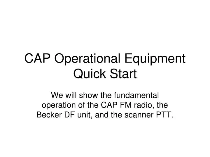
CAP Operational Equipment Quick Start. We will show the fundamental operation of the CAP FM radio, the Becker DF unit, and the scanner PTT. Technisonic TDFM-136 Radio. Power Up.

E N D
CAP Operational Equipment Quick Start We will show the fundamental operation of the CAP FM radio, the Becker DF unit, and the scanner PTT.
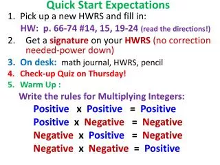
Power Up • To power up the Technisonic TDFM radio make sure the Mission Radio toggle switch is in the on position. This switch is located just to the right of the co-pilots side control yoke. • The Main switch is turned on and set to a mid-volume level. • The Guard volume switch is turned down. • The MN/GD switch is set to MN. • The HI/LO switch is in the HI position. • If you get in trouble with a command, press the */ESC key to escape the command.
Channel Selection • The FM radio is pre-programmed with appropriate CAP frequencies. See the communications section of the aircraft book for the channel plan • To select a channel by channel number, press the 1/CHAN key and enter a 3 digit channel (001 to 200) using the numeric key pad. To accept the entry, press the #/ENTER key. To abandon the selection, press the */ESC key. Note the MN/GD switch MUST be in the MN position.
Channel Selection cont. • To scroll through channels use the 4 and 6 keys to scroll backwards and forwards through the channels.
Talking on the radio • The TDFM radio is FM-1 on the audio panel. • To monitor the FM radio, toggle the toggle switch to the FM1 position. • To transmit on the FM radio, move the TX rotary switch to the FM1 position. Note that the TX rotary switch automatically sets the receive mode. • The PTT switch will now transmit on the FM radio when pressed.
Display Brightness • To adjust the display brightness, use the 2 and 8 keys to increase/decrease the display brightness
I’m Stuck • The TDFM radio is pre-programmed for CAP frequencies. • Do not use the 7/FREQ key unless you know what you are doing. If in doubt, use the */ESC key to get out of any command. • If the keypad appears not to be responding, it may be locked. To unlock the keypad, hold the */ESC key for two seconds. This should unlock the keypad. • Note the complete manual for the TDFM-136 can be downloaded from http://www.til.ca/download/tdfm136_install.pdf
Becker SAR DF-517 • The Becker SAR DF-517 is an automatic direction finder. It supports 121.5, 243 and 406 MHz frequencies. • The DF unit will display a bearing relative to the nose of the aircraft for signals received. • There are two sets of frequencies that may be selected. These are Emergency Mode or Training Mode frequencies. • The Emergency Mode or Training Mode can only be selected at power up.
The Mission Power switch must be on for the DF unit to operate. On power up (1), the user must verify Emergency or Training mode. To change the setting, turn the page dial (2) and select the appropriate mode (3). Note that power up is the only way to switch between Emergency and Training Mode. This will be displayed for a few seconds at power up and will retain this mode on power down. Power Up
Initial Setup • The Page dial (2) is used to switch the DF-517 between the different pages. • By holding the Rep button and rotating the page dial (1) the brightness can be adjusted.
DF-517 DFing • Select the desired frequency to DF by using the bottom right rotary dial (1) to select the desired preprogrammed frequency. • Use the volume (2) rotary dial to set the volume level. • Once the desired frequency is selected, use the SQL (3) dial to select the squelch level.
DF-517 DFing cont. • The DF signal can be heard by selecting the ADF monitor toggle on the audio panel. • DFing is done using Page 1 or Page 2. • Page 1 displays a full circle with the signal and bearing in 360o. • Page 2 displays a 45o window with the relative bearing and signal.
DF-517 DFing cont. • (1) The signal and relative bearing • (3) Signal Strength • (4) Squelch level • Tracking frequency 406.025 in Emergency mode. • Note that to DF a signal, the squelch level must be below the maximum signal strength. DF-517 Page 1 Display
DF-517 DFing cont. • (1) Signal level and relative bearing • (2) Position error • Tracking Freq. 121.650 in Training Mode DF-517 Page 2 Display
DF-617 Adjusting Frequencies • Page 6 enables you to adjust the training frequencies. • (1) >±Select< rotary switch selecting the trainings-frequency (MHz/kHz). • (2) >±< rotary switch changing the frequency. Confirm the changed value by pressing pushbutton >STORE< . • (3) >STORE< Pushbutton to confirm changed values.
DF-517 • The backlight is controlled by adjusting the top panel light adjustment and setting the annunciator panel switch in the “Night” position. • Additional information on the Becker DF-517 can be found in the manual. This can be found online at: http://www.becker-avionics.de/666571_C_Images/ImgProductsUSA/ProductsUSAPDF/ACF564.pdf
Scanner PTT • The aircraft has a PTT toggle switch, a 12 Volt auxiliary adapter and an external antenna with a BNC type connector located next to the pilot side rear seat (the scanner position). • The 12 Volt auxiliary power is controlled by both the CAP Mission toggle switch and the 12 volt toggle switch right next to the copilot’s control yoke.
Scanner PTT cont. • A cigarette lighter adapter is provided for the power port and a BNC cable is provided for the external antenna. • The PTT switch will transmit on the radio selected by the transmit selector for the copilot on the audio panel. • When the scanner PTT switch is in the TX mode it overrides the observer PTT switch and it also disables the intercom for all crew members.
Conclusion • Let’s be safe out there. • Good luck and happy DFing!