Download
1 / 140
1.4k likes | 1.61k Views
MPEG4 Digital Video Recorder. Real Time Recording MPEG-4 DVR PREMIUM DVR STANDARD DVR COMPACT DVR. ~ Real Time Recording. Professional Model ~. Professional Digital Video Recorder. CONTENT. NOTICE 1.1 NOTICE --------------------------- -- ----------- -- ----4 OVERVIEW

E N D
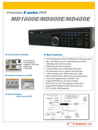
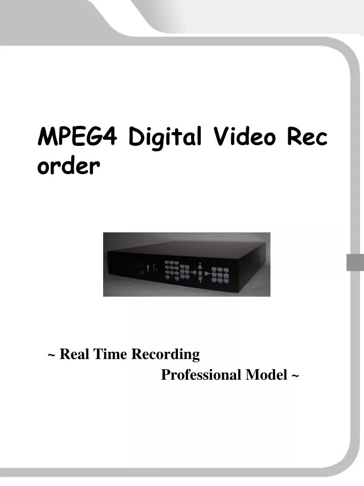
MPEG4 Digital Video Recorder Real Time Recording MPEG-4 DVR PREMIUM DVR STANDARD DVR COMPACT DVR ~ Real Time Recording Professional Model ~ Professional Digital Video Recorder
CONTENT NOTICE 1.1 NOTICE----------------------------------------------4 OVERVIEW 2.1 FEATURES-------------------------------------------7 2.2 PACKING DETAILS-----------------------------10 2.3 NAMING AND FUNCTIONS-------------------11 2.3.1 FRONT PANEL--------------------------------11 2.3.2 REAR PANEL----------------------------------12 2.3.3 REMOTE CONTROLLER------------------14 2.3.4 Q-MENU-----------------------------------------15 2.4 SPECIFICATION----------------------------------16 INSTALLATION 3.1 TOTAL CONNECTION DIAGRAM----------18 3.2 INDIVIDUAL CONNECTION------------------19 3.2.1 POWER-----------------------------------------19 3.2.2 VIDEO & AUDIO----------------------------- 20 3.2.3 HDD CONNECTION------------------------ 24 3.2.4 EXTERNAL CONNECTOR--------------- 26 OPERATION 4.1 PRE-OPERATION----------------------------- 4.2 POWER CONNECTION---------------------- 4.3 LIVE DISPLAY--------------------------------- 4.3.1 SINGLE DISPLAY------------------------- 4.3.2 MULTIPLE DISPLAY---------------------- 4.4 AUTO SEQUENCE --------------------------- 4.5 DIGITAL ZOOM------------------------------ 4.6 PIP---------------------------------------------- 1 29 30 32 32 33 37 38 39
CONTENT CONTENT 40 41 42 44 45 45 47 47 48 48 51 53 54 55 57 4.7 SPOT---------------------------------------- 4.8 PTZ------------------------------------------ 4.9 MOUSE------------------------------------- 4.10 OSD---------------------------------------- 4.11 RECORDING----------------------------- 4.11.1 NORMAL RECORDING------------ 4.11.2 EVENT RECORDING---------------- 4.11.3 SCHEDULE RECORDING----------- 4.12 SEARCH----------------------------------- 4.12.1 NORMAL SEARCH------------------ 4.12.2 EVENT SEARCH--------------------- 4.12.3 TIME SEARCH------------------------ 4.12.4 JOG SHUTTLE SEARCH------------- 4.13 BACK UP---------------------------------- 4.14 BACK UP VIEWER----------------------- SETUP MENU 5.1 FACTORY DEFAULT----------------------- 5.2 QUICK SETUP------------------------------ 5.2.1 LANGUAGE ---------------------------- 5.2.2 RESOLUTION--------------------------- 5.2.3 QUALITY-------------------------------- 5.2.4 OVERWRITE--------------------------- 5.2.5 PRE-RECORD-------------------------- 5.2.6 REMOTE ID---------------------------- 5.3. CAMERA---------------------------------- 5.3.1 CHANNEL------------------------------- 5.3.2 TITLE------------------------------------- 5.3.3 ADJUST---------------------------------- 5.3.4 PTZ PROTOCOL------------------------ 5.3.5 PTZ BAUDRATE------------------------ 5.3.6 PTZ SPEED------------------------------ 5.3.7 PTZ ID----------------------------------- 2 59 61 61 61 62 62 62 62 63 63 64 65 65 65 66 66
5.8.7 INFORMATION--------------------------99 5.8.8 RESET------------------------------------101 5.9 UPDATE---------------------------------------102 5.9.1 USB UPDATE-------------------------- 102 5.9.2 NETWORK UPDATE------------------103 5.9.3 UPDATE----------------------------------104 MULTI NETVIEWER PROGRAM 6.1 DEFINITION------------------------------- 6.2 NET VIEWER SET UP------------------- 6.2.1 INSTALLATION------------------------ 6.2.2 PROGRAM REMOVAL--------------- 6.2.3 NET VIEWER FUNCTION------------ 6.3 WEB VIEWER----------------------------- 6.3.1 MAC ADDRESS ON IE (INTERNET EXPLORER)------------ 6.3.2 PLAY BACK----------------------------- 6.3.3 MULTIPLE DISPLAY------------------- TROUBLE SHOOTING----------------------135 WARRANTY--------------------------------------138 67 67 68 69 70 70 71 71 75 75 79 80 81 81 81 82 83 86 86 87 87 88 88 90 91 92 92 93 93 94 95 97 98 98 5.4 DISPLAY----------------------------------- 5.4.1 SEQUENCE---------------------------- 5.4.2 OSD DISPLAY------------------------- 5.4.3 VIDEO LOSS-------------------------- 5.4.4 SPOT----------------------------------- 5.4.5 VIDEO FORMAT---------------------- 5.5 RECORD---------------------------------- 5.5.1 RESOLUTION------------------------- 5.5.2 WATERMARK------------------------- 5.5.3 SCHEDULE SETUP------------------- 5.5.4 AUDIO---------------------------------- 5.5.5 OVERWRITE--------------------------- 5.6 EVENT-------------------------------------- 5.6.1 SENSOR-------------------------------- 5.6.2 SENSOR IN---------------------------- 5.6.3 MOTION------------------------------- 5.6.4 MOTION SET-------------------------- 5.6.5 ALARM--------------------------------- 5.6.6 RECORD TIME------------------------- 5.6.7 POP UP--------------------------------- 5.6.8 PRE-RECORD-------------------------- 5.7 NETWORK SETUP----------------------- 5.7.1 IP SETUP------------------------------- 5.7.2 DDNS----------------------------------- 5.7.3 E-MAIL--------------------------------- 5.7.4 DVR NAME--------------------------- 5.7.5 DVR LOCATION---------------------- 5.8 SYSTEM----------------------------------- 5.8.1 LANGUAGE--------------------------- 5.8.2 DATE/TIME--------------------------- 5.8.3 USER SETUP------------------------- 5.8.4 HDD FORMAT----------------------- 5.8.5 CONTROLLER------------------------ 5.8.6 SYSTEM LOG------------------------- 105 105 105 109 111 132 132 133 134 3
NOTICE NOTICE BEFORE INSTALLATION This manual serves basic operation on installation, and operation of DVR (Digital Video Recorder). User who first operates DVR, or is not accustomed to use is strongly recommended to contact manufacturer, or supplier while installation, and to use in order to receive the technical service. All users have to operate DVR after having read this manual sufficiently even though they are very skilled at this unit. Please keep notice at this manual to protect your safety from danger, or property. Please keep this manual on such a place where can easily be reached after having read it all. NOTICE FOR SAFETY Please make sure of usage after bearing the following contents in mind to shorten the safety, and product failure before its operation. 4
DO NOT SHOCK IN MOVE, AND INSTALLATION. ▪ Please check rating voltage (standard:DC12V5A, high-end:12V8A) before power on. ▪ Please check power off before installation. ▪ Avoid any place with moisture because of electric shock, and fire. ▪ Avoid any place with moisture, dust, or soot. ▪ Avoid any place with direct sunlight, or heating appliances. ▪ Avoid high, or low temperature. ▪ Procure sufficient air ventilation for the connection of system wiring. ▪ Don't install near to electronic devices such as radio, or TV. ▪ Install in sufficient air ventilation, and no vibration. ▪ Please take care of not putting the electric product into the cooling fan. ▪ Don't use water, or cleanser in surface cleaning to prevent an electric shock . ▪ Please clean system by dry towel in external cleaning. ▪ Do not pull power cord forcefully. ▪ Do not place any heavy objects on the main system. ▪ Do not open, or disassemble DVR without an assistance of qualified service personnel. ▪ Please power off in case of moving DVR. ▪ Please equip with the safety facility to diminish the loss for electricity failure, and lighting. ▪ Do not connect signal cable of camera with DVR system during camera installation. ▪ Please power off immediately, contact manufacturer, or supplier if you catch strange scent, or smog. 5
This equipment had been tested and found to comply with the • limits for CLASS A digital deice, pursuant to Part 15 of FCC • Rules. These limits are designed to provide reasonable • protection against harmful interface when the equipment is • operated in a commercial environment. • FCC Compliance Statement • Caution : Any change, or modification in construction of this device which are not expressly approved the party responsible for compliance could avoid the user‘s authority to operate the equipment . • NOTE : This equipment has been tested, and found to comply with the limits for a Class A digital device, pursuant to part 15 of the FCC rules. This limits are designed to provide reasonable protection against harmful interference when the equipment is operated in a commercial environment. This equipment generates, uses, can radiate radio frequency energy, and , if not installed, and used in accordance with the instruction manual, may cause harmful interference to radio communications. • Operation of this equipment in a residential area is likely to cause harmful interference in which cause the user will be required to convert the • interference at his own expense. 6
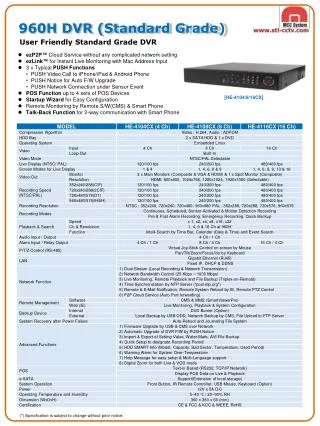
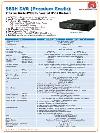
OVERVIEW 2.1 FEATURES 1. SURVEILLANCE ► Real time moving picture (Max. MPEG-4 480 Frame (Basic 16CH)) . ► Multi screen display (Basic on 16CH): Single / 4 / 6 / 9 / 13 / 16 . ► PIP (Picture In Picture) . ► Auto sequence. ► Multi output monitor (Output monitor 1, Spot 1, S-Video 1, VGA 1). ► PTZ (Pan / Tilt / Zoom). ► Digital Zoom (X2) ► Mosaic function . ► Video loss sensor detection. ► External alarm, and recording event list for motion detection. ► Supported user friendly GUI interface, remote controller, and mouse. 2. RECORDING ► Recording in high quality of MPEG-4 real time motion picture ► Recording resolution setup adjustable to backup capacity (16CH Max. 480 frame) ► Multi recording for manual, event, and schedule. ► One time system for display, recording, playback, backup, and network. ► Easy setup for recording resolution, and motion detection part. ► Supported manual, and reserved recording function. ► Supported Individual channel recording. 7
3. PLAYBACK ► Playback by event, time, and channel. ► Mouse controlled search ► Playback for still image, and search for still display detection. ► Playback by event list (sensor, motion). ► Easy search with remote controller, and mouse. ► Digital zoom in playback display screen (Digital Zoom X2) 4. NETWORK ► Supported PPPoE, Static and DHCP. ► Supported itself, and general DDNS. ► TCP/IP. ► Unlimited multi access (Recommended 10). ► Supported multi mode (LIVE/PB/NETWORK BACKUP/FILE PLAY) ► Multi DVR Control ► Remote Control ► PTZ Control ► Save AVI ► Save & print still ► Auto update ► Web viewer ► File viewer ► Multi network viewer ► CMS network viewer 8
5. AUDIO ► One time recording for real time 4CH audio input. ► Input : 4CH(rear 4), Output : 1ch(rear). ► Audio channel selectable. 6. BACKUP ► Backup by network viewer. ► Supported multi backup function : CD±R,CD±RW,DVD±R,DVD±RW and USB. 7. OTHERS ► S-Video, Spot output. ► Alarm In/Out, RS-485, RS-232 Connections. ► Connection of loop-through. ► Supported multi language. ► One remote controller for Max. 4 DVRs. ► Easy operation with USB mouse. ► Easy firmware upgrade with USB, network and webhard. 9
DVR Unit: 2.2 PACKING DETAILS DVR includes main unit, and its following accessories in the package packing. Please check all items if there is all packed inside as below. Please contact manufacturer, or supplier if found missing accessories. 10 Accessories: • Program CD • Remote controller • User manual • Batteries • Power cord • Adaptor • HDD Screws • SATA HDD Cable
STANDARD DVR 11
2.3.2 REAR PANEL STANDARD DVR 16CH 12
STANDARD DVR 8CH 13 4CH
2.3.4 Q-MENU 15
STANDARD DVR 16
INSTALLATION 3.1 TOTAL CONNECTION DIAGRAM 18
3.2 INDIVIDUAL CONNECTION 3.2.1 POWER Please connect adaptor with socket as below 19 NOTE 1. Please connect a rate adaptor with DVR system. 2. After pressing the power button on front panel, and checking message on monitor, please separate power socket from DVR system in case of power off.
3.2.2 VIDEO & AUDIO VIDEO INPUT Please connect DVR, and CCTV camera with CAMERA IN connector on rear panel by coaxial cable. This DVR system can be connected with cameras of maximum NO. of 16/8/4. 20
CAUTION 1. Video vibration is possible when user connects BNC of camera with loop connector without connecting input connector. Be sure to link it to camera input connector. 2. Too much vibration is possible in case of not linking BNC connector to camera output without connecting camera cable. NOTE 1. Video input type should be either NTSC or PAL, Don't use two types in mix. 2. Automatic setup for 75Ω resistance 75Ω terminal resistance is set up, automatically split into, and becomes Hi-Z status when connected with video output connector under input one. 21 VIDEO OUTPUT Please connect DVR with monitor by video cable.
[AUDIO INPUT CONNECTORS] PREMIUM DVRCOMPACT DVR STANDARD DVR [AUDIO OUTPUT CONNECTORS] NOTE Please select AUDIO IN channel on recording setup in case of setting up audio input. AUDIO INPUT Please connect with jack MIC built-in camera in AUDIO IN connector, or external audio device at the back of this DVR. 22 In audio output, default channel color is in red color.
NOTE 1. Four audio input synchronizes audio output for CH1~CH4 in single display. 2. Audio is possible to live, and play back display mode in playback. 3. Audio is not supported in double playback in single display mode. AUDIO OUTPUT Please connect RCA of speaker built-in monitor in audio out connector at the back of this DVR. 23
3.2.3 HDD CONNECTION ► Please fix HDD to DVR unit by screws. ► Please connect main board with HDD power cable. ► Please assemble DVR, power on after connecting main board with HDD data cable. POWER CABLE 24 DATA CABLE Auto format starts after power on. If not, [ System setup ] 4. HDD format => "Yes"
NOTE 1. For HDD connection with DVR unit system, please be sure to power off. 2. For fixing screw to HDD bracket, please don't shock, which may cause HDD breakdown. 3. Please check problem after HDD installation. 4. For HDD problem, or not recognized, please contact manufacturer, or Supplier, and change it into new one. Recording is not properly worked. 5. All data disappear in HDD installation, which is not in the type of format. 6. The firmware upgrade is available only in the HDD connection. 7. When connecting HDD (or additional HDD) to DVR, please be sure to connect data cable to HDD port on main board. If being connected to DVD port, recording data may be damaged. 25
NOTE User can set values in menu as he wants 3.2.4 EXTERNAL CONNECTOR SENSOR IN / RS-485 As external sensor terminal, input information is input from connected sensor, or DVR . Connector to output to the external alarm information of sensor motion, motion detection, and video loss. RS-485 26
NOTE User can set values in menu as he wants RS-232 Connector through external controller. 27
ETHERNET & USB • 1) USB • 2) ETHERNET 28
OPERATION 4.1 PRE-OPERATION Please make sure of power voltage before power on. 4.2 POWER CONNECTION ▮ POWER ON Please make sure of power voltage before power on. 1. Connect DVR to D/C power Jack by using adaptor in the package. 2. Having finished the connection between power cable and external device, power is on by pressing button on the rear panel. The following display appears. 3. Booting time takes about 30 seconds after power is on. 4. Video signal is automatically detected when power is on. 5. The menu values set by user is not changed in sudden power failure. 29
CAUTION 1. User is strongly recommended to use the adaptor in the package that manufacturer provides. 2. The DVR may be fatally damaged by use of different voltage of adaptor. ▮ POWER OFF Press red POWER button on front panel. Its function is mainly to prevent system damage due to suddenly unexpected power off. Pull off adaptor on rear panel when the message appears below. 30 39 Select YES to power off. System is closing. In this process, user can not return to "power on" mode.
CAUTION "STOP RECORDING" message shows up on monitor when being pressed during recording. Pull off adaptor on rear panel when this message appears. 31
NOTE If pressing +10 button twice or any channel button is not followed for about 2 seconds after pressing +10 button, it goes to channel 10. 4.3 LIVE DISPALY 4.3.1 SINGLE DISPLAY When user selects one channel in multiple channel mode, this channel is switched over to single channel mode as below. User needs to press one more channel button after +10 button when he selects over channel 10. For example, he needs to press channel 1 Button after +10 Button when selecting channel 11. This channel selection method is the same as both live mode and playback mode. 32 [Full multiple channel ] [Single channel ]
Event recording on Audio on Recording on Network online NOTE For more details, please refer to Q.menu set up. 4.3.2 MULTIPLE DISPLAY LIVE DISPLAY SCREEN Current date and time DVR status icon 33 Quick menu
NOTE User can play the recording data frame by frame by pressing REW or FF button in playback mode. In 16 multiple channel, user can move to channel 1 by pressing digital zoom button. PLAYBACK DISPLAY MODE Up: Live time Down: Recorded date and time Play back mode 34 Play back speed control icon ▶ /▮▮ : PLAY / PAUSE ◀◀ : REW ■ : STOP ▶▶ : FF : DIGITAL ZOOM
NOTE User can move to next channel by clicking the right button of mouse in single mode. To return to divided channel mode, user needs to press on quick menu or DISPLAY button on front panel. Press DISPLAY button, and full divided channel mode is switched over to real-time surveillance display mode. 1. Auto sequence or PIP mode can be switched over to 16 channel display mode by pressing DISPLAY button. 2. Live mode is switched over to 16 channel display → 13 channel display → 9 channel display → 6 channel display → 4 channel display mode in order by pressing DISPLAY button, or clicking the right button of mouse repeatedly. 35 13 channel display → 9 channel display → 6 channel display → 4 channel display The display channel can be changed by pressing UP/DOWN button in divided channel mode as desired.
NOTE This mosaic function is only available at live display mode. MOSAIC FUNCTION User can make certain area in live mode blurred for private purpose. Mosaic ON Mosaic OFF 1. Select one channel that user likes to set up. 2. Put the mouse at the starting point you want, and drag it to the desiring area with left-button pressed. 3. This mosaic function is only available in display mode, and does not affect any recording data even if it is on when recording is triggered. 4. To release this function, drag mouse diagonally from the right bottom of set area with it pressed. 36 Mouse starting point
4.4 AUTO SEQUENCE (AUTO) Live mode is automatically switched over to single channel or 4 channel mode with time interval that is set in display, and auto display mode in AUTO button pressing. - Display mode setup : Menu > Display > Sequence > Mode : single or quad - Interval setup : Menu > Display > Sequence > Interval : 1 sec ~ 60 sec. Press the button again, and DVR stops this function. ▶ To release this AUTO function, press DISPLAY button. ▶ DVR skips the channel with no video when this function is triggered. [ Single channel ] [ 4 channel ] CH1 CH2 CH3 CH4 . . . CH1 ,2,3,4 CH5,6,7,8 CH9,10,11,12 CH13,14,15,16 . . . 37
4.5 DIGITAL ZOOM User can magnify the area that he wants 2 times digitally. 38 1. Click on Q.MENU and select the area that you want by pressing direction key buttons. 2. Press ENTER button, and the picture inside angle is magnified digitally. This function is only available at single channel . 3. To release this function, press the ZOOM button again.
4.6 PIP ▶ User can monitor small channel together in single channel mode. ▶ User can monitor main channel and sub channel together in single channel mode. ▶ Various PIP modes are displayed when pressing PIP button repeatedly. ▶ The sub channel location is changed when pressing PIP button, or clicking the right button of mouse. 39 ▶ The sub channel display is changed when pressing LEFT / RIGHT button of direction key on front panel. ▶ The main channel display is changed when pressing UP / DOWN button of direction key on front panel. ▶ To stop this function, press DISPLAY button.
4.7 SPOT [SPOT monitor] 40 1. This function leads to only monitor additional monitor as well as main monitor . Main monitor offers all functions of DVR like menu set up, live video display (divided channel display) , and playback. But SPOT monitor supports only live single channel, or live 4 channel display. 2. SPOT monitor also supports AUTO SEQUENCE function, and can set up time interval as user wants.
4.8 PTZ PTZ set up is required in menu set up, and PTZ is used for controlling camera with PAN/TILT/ZOOM/FOCUS. 1. Press PTZ button in live divided 16 channel mode, and single channel mode appears. 2. Press ENTER button, and move to each menu like CH, P/T, Z/F. 3. PTZ camera is controlled with LEFT / RIGHT buttons on front panel, mouse, or remote controller. 4. To release this function, press PTZ button again. 41 ① CH : Channel change ② P/T : PAN & TILT control ③ Z/F : ZOOM & FOCUS control To function above, please setup PROTOCOL, BAUDRATE, SPEED, ID from MAIN MENU>CAMERA.
RIGHT BUTTON LEFT BUTTON CAUTON NOTE Make sure that PTZ speed dome camera is properly installed on the relevant channel before PTZ operation. PTZ mode is available at live single display mode only, not controlled by divided channel display mode. MOUSE WHEEL To release this function, press PTZ button again. 4.9 MOUSE By using USB mouse, setting values can easily be adjusted, or changed. ▮ MOUSE OPERATION 42
▮ KEY BUTTON OPERATION ON FRONT PANEL 1. ◀▶ : To move cursor to left, or right 2. ▼▲ : To move cursor to up, or down 3. : ENTER button. To activate the corresponding function. 4. Q.MENU : To get out of current menu ▮ Remote controller operation 1. ◀▶ : To move to left or right 2. ▼▲ : To move to up or down 3. : ENTER button. To activate the corresponding function 4. Q.MENU : To get out of current menu 1. Left button ① To select menu or to confirm setting value ② To move to 16/13/6/4 CH in display screen mode ③ To revert into the previous multiple screen mode from 1 CH single screen mode 2. Right button ① In display screen mode 13 multiple screen mode : To move to next channel by one channel. 9 multiple screen mode : To move to 1-9 channel and 8-16channel 6 multiple screen mode : To move to next channel by one channel 4 multiple screen mode : To move to 1-4, 5-8, 9-12, 13-16 channel ② To move to next channel from single channel in play back mode ③ To change sub-channel in PIP mode 43
4.10 OSD ► Time, channel name, and motion activating icon can disappear in order in display mode. Press OSD button on front panel , or button on Q.MENU by stage. [OSD ON] [OSD OFF] 44
CAUTON 1. Factory default is set to function the schedule recording . 2. In recording release, record setup should be released from schedule record menu. 3. In release of schedule recording, REC button on front panel can be set, and recording releases. NOTE 1. Password approval is pre-requisite to stop recording. 2. In the mode of record setup menu, auto recording is effected at the time user wants. (Please refer to schedule record setup from setup menu.) 4.11 RECORDING 4.11.1 NORMAL RECORDING Press REC button, and LED is lighted with red color. Recording starts with record icon and appeared at the right upper side. To release recording, press REC button again and record icon also disappeared accordingly. When recording starts, or releases, the message of START RECORDNG appears, and disappears at the bottom of right side. 45
4.11.2 EVENT RECORDING Event recording is automatically reserved according to time, and date when event setup is set to record setup mode in system setup menu. 4.11.3 SCHEDULE RECORDING Schedule recording is automatically played according to time, and date to be set when schedule setup is set to schedule setup mode in system setup menu. 47
4.12 SEARCH Press SEARCH button on front panel, and the following SEARCH menu appears on screen. Recorded video can be searched, and play backed by NORMAL search (time, and date), by EVENT,and by TIME, performing recording&searching simultaneously. To cancel recording search, and to get back to live display mode, press SEARCH button repeatedly. 48 4.12.1 NORMAL SEARCH (DATE, AND TIME SEARCH) ① After pressing SEARCH button, move to the date with yellow color, and press ENTER button.
NOTE 1. Press MENU button to move to normal search, event search, and date search. 2. Move monthly moving search by pressing UP/DOWN direction key button. 3. The yellow area means recording date in search menu. 4. Search is possible after checking playback to this area. ② When time graph appears, move to the time user wants, and press ENTER button while time is in yellow color. ③ When minute graph appears, move to the area in yellow color, and press ENTER button at the area you want. 49 ④ Recorded video is played back at selected date ** To stop search, and to return to live display mode, press STOP button.