Download

1 / 2
20 likes | 159 Views
Worldwide PIV Challenge 2003 German Aerospace Center (DLR). Busan, Korea September 19-20, 2003. www.pivchallenge.org. Image distortion PIV based on B-Splines *. *) or: YAPA = Y et A nother P IV A lgorithm. Chris Willert Institute of Propulsion Technology, DLR, 51170 Köln, Germany.

E N D
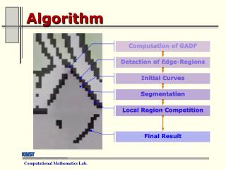
Worldwide PIV Challenge 2003 German Aerospace Center (DLR) Busan, Korea September 19-20, 2003 www.pivchallenge.org Image distortion PIV based on B-Splines * *) or: YAPA = Yet Another PIV Algorithm Chris WillertInstitute of Propulsion Technology, DLR, 51170 Köln, Germany Overview Algorithm AbstractThe algorithm used by DLR for the PIV-Challenge is a combination of pyramid-based grid refinement (multi-grid, see e.g. Willert, 1997) and full-field image deformation which is intended to give second-order accurate displacement data. At its core a standard FFT-based correlation algorithm provides local image shift data. Special emphasis was placed on striking a balance between accuracy, robustness and processing speed. The specific characteristics of this algorithm, whose flowchart is shown on the right, will be given in the following sections. Image Pre-Processing The images from Cases A and C both benefit from image enhancement prior to correlation processing. High-pass filtering and/or dynamic histogram equalization reduce background noise and thereby increase correlation peak visibility. Multi-Grid-Processing A typical processing pyramid may look as follows: 1st pass : 96 96win, 48 48step (50% overlap) 2nd pass : 64 64win, 32 32step (50% overlap) 3rd pass : 32 32 win, 16 16step (50% overlap) 4th pass : 16 16 win, 8 8step (50% overlap) Final pass : 16 16 win, 8 8step (50% overlap) One unique feature here involves down-sampling the image instead of using larger interrogation windows. This down-sampling is performed by summing up the intensities of neighboring pixels without clipping the result – that is, image intensities are preserved at a reduced spatial resolution. In effect small and fast interrogation windows (typ. 3232 px) then may be re-used throughout the first iterations. Aside from speeding up the processing with smaller windows the same validation criteria (e.g. correlation peak search area, median filtering, etc.) may be used throughout. After validation the new displacement data is projected onto the next finer resolution using bilinear interpolation. For added stability the intermediate data is smoothed with a 33 kernel. To improve convergence, the interrogation at the final resolution is once repeated. Peak Detection Generally the three highest correlation peaks are located from a limited region of interest in the correlation plane. In the final processing passes, a Levenberg-Marquardt nonlinear least-squares fit to the correlation peak is performed for sub-pixel peak location using 77 values. The procedure is described by Ronneberger et al. (1998). Image Samples Grid RefinementPyramid Processing Flow Chart (taken from Case Bnear bottom edge) Start 6464 3232 1616 1616 (Final Pass) 64 pixels Note that images are shifted toward each other using half the displacement for each.
How to increase speed Image interpolation After each interrogation pass the displacement data is used to deform the image data by applying half the local shift to each image in opposite directions. Bi-linear interpolation is used to sample the displacement data which gives room for further improvement.Unique here is the use of B-splines (B= basis or basic) for the interpolation of the displaced images which was found to give superior performance with respect to polynomial or cardinal sinc interpolation. One side effect in high gradient particle image data is that the interpolated image may take on negative values or overshoot (=ringing). The effect increases for under-sampled images. • apply image deformation to entire image rather than to each interrogation window • delay precision peak detection until final pass • detect only strongest correlation peak during initial passes • limit correlation peak search area • delay image deformation until final pass • image down-sampling to reduce correlation window size • employ dimensional separability of many image operations (use 2 1-D in place of 2-D) • use FFTs whenever possible • take advantage of Fourier transform symmetry properties (i.e. real-to-complex FFTs) • re-use spline coefficients (e.g. need only be calculated once for original images) • use bilinear image interpolation for intermediate passes • (choose a processing platform with large CPU cache and fast memory access as full frame image deformation is more memory intensive than localized image deformation) Interpolation function shapes:solid line = cubic B-Splinedotted: linear interpolator Generalized interpolation:(ßn(x) = synthesis function)For linear interpolation: c(k) = image samplesand For cubic B-spline: Equivalent interpolant of cubic B-spline Note : Here c(k) are coefficients, not image samples! These are calculated a-proiri for the original images using a forward-backward recursive filter which requires 2 additions and 2 multiplications per coefficient (e.g. fast computation).(Thévenanz et al., 2002) Non-separable 2-D interpolation using 55 points (25 function evaluations) Separable 2-D interpolation using 55 points (25=10 function evaluations) (Figures in part from Thévenaz et al., 2000) Conclusions • Improvement possibilities / open issues: • The potentials of B-splines for PIV processing have not yet been fully exploited. • Further work may include: • improved displacement field interpolation schemes during the image distortion steps • use of B-splines to artificially increase image resolution (Fincham & Delerce, 2000) • quantify the performance of the different image interpolation schemes. (It was observed that a 5th order B-spline sometimes produced noisier results than a 3rd order B-spline) • improved intermediate data validation (to increase robustness to image quality) Processing of all three data sets was performed with the same algorithm with slight variations in image pre-processing, peak-detection ROI and validation parameters. The results provided for the PIV-Challenge were intended to strike an optimum between high-spatial resolution and high validation rates on the one hand, and reasonable noise levels and processing speed on the other. A higher spatial resolution would have been possible but at the cost of increased noise. Alternatively, the noise could have been further reduced through massively over-sampled PIV interrogation – which significantly increases processing times. Finally, image interpolation based on B-splines was found outperform traditional techniques (i.e. polynominal or sinc-based interpolation) both in terms of speed and precision. Acknowledgments References [1] C. Willert (1997), “Stereoscopic digital PIV for application in wind tunnel flows”, Measurement Science and Technology, vol. 8, pp. 1465-1479. [2] O. Ronneberger, M. Raffel, J. Kompenhans (1998), “Advanced evaluation algorithms for standard and dual plane PIV”, Proc. 9th Intl. Symp. on Appl. of Laser Techniques to Fluid Mechanics, Lisbon, Pt, July 13-16. [3] P. Thévenaz, T. Blu, M. Unser(2000), “Interpolation revisited”, IEEE Transaction on Medical Imaging, vol. 19, no. 7, pp. 739-758. [4] A. Fincham, G. Delerce (2000), “Advanced optimization of correlation imaging velocimetry algorithms”, Experiments in Fluids, vol. 29, no. 7, pp. S13-S22. The PIV-Challenge image data sets were entirely processed with the PIVview software package (PIVTEC GmbH, Germany). PIVTEC is a DLR out-sourcing enterprise founded in 2001 and is dedicated to making PIV-related developments of DLR commercially available. A demo version of PIVview may be downloaded from www.pivtec.com Göttingen Germany