Download
1 / 33
340 likes | 534 Views
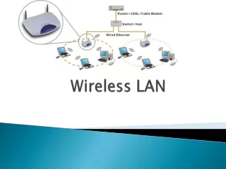
Wireless LAN (WLAN). Wireless Ethernet Bluetooth. Introduction. Demand for wireless device connection has been growing WLAN is generally used in campus, office as well as in cafe, petrol station etc. WLAN can also be fixed at home for usage of Internet connection in other mobile devices.

E N D
Wireless LAN (WLAN) • Wireless Ethernet • Bluetooth
Introduction • Demand for wireless device connection has been growing • WLAN is generally used in campus, office as well as in cafe, petrol station etc. • WLAN can also be fixed at home for usage of Internet connection in other mobile devices
IEEE 802.11 • 802.11 standard define specification that cover physical and data link layer for WLAN • Architecture • Physical layer • Media Access Control Layer (MAC) • Addressing mechanism
WLAN architecture: Basic Service Set (BSS) • BSS defined as building block of WLAN • Made of mobile wireless stations and an optional central base station (access point -AP) • BSS without an AP is stand alone network and cannot send data to other BSSs. (called: ad-hoc architecture) • Stations can locate one another and agree to be part of BSS
WLAN Architecture: Extended Service Set (ESS) • ESS is made of >= 2 BSSs with APs • Generally, BSSs are connected through a distribution system (wired LAN) • Distributed system connects the APs in the BSSs. • IEEE 802.11 doesn’t restrict the distribution system : It can be any IEEE LAN (such as Ethernet) • Stations in ESS: mobile & stationary • Mobile: normal stations inside a BSS • Stationary: AP stations that are part of a WLAN • When BSSs are connected, this architecture called infrastructure network, and stations in BSS no need AP to communicate one another • However communication between 2 stations from 2 difference BSSs normally occur through 2 APs
Stations types • IEEE 802.11 defines 3 type of stations based on their mobility: • No-transition • Stationary or moving only inside a BSS • BSS-transition • Move from one BSS to another, but the movement is confined inside one ESS • ESS-transition • Move from one ESS to another but IEEE 802.11 doesn’t guarantee that communication is continuous during the move
Physical Layer Specification • IEEE 802.11 defines specification to convert bit to signal (physical layer) • There are 5 type of specification in radio frequency domain
Frequency Hopping Spread Spectrum • Generating signal in 2.4 GHz ISM band • Data transmission using 1 frequency carrier for certain period and hop to another frequency and so on. • After N hops, loop will be repeated. • If initial bandwidth signal is B, spread spectrum bandwidth is : N x B • data rate: 1 @ 2 Mbps, use FSK modulation at 1M baud/s
Direct Sequence Spread Spectrum • Also in 2.4-GHz ISM band (industrial, scientific, medical) • Each bit that sent replaced with bit sequence (chip code) • To prevent the use of buffer, the time to send a chip code should = time to send original bit • If number of bit in each chip code = N, data rate to send code chip = N x original stream bit data rate • Not same as CDMA because this is physical layer implementation • bit sequence use overall band • Data rate 1 @ 2 Mbps, use PSK modulation at 1Mbaud/s
MAC sub-layer in IEEE 802.11 standard • 2 MAC sub-layer • Distributed coordination function(DCF) • Point coordination function (PCF) – more complex for just infrastructure network
CSMA/CA and Network Allocation Vector • NAV is CA implementation method • When RTS is sent by 1 station (including time period that needed to use channel) • Other station will start respective NAV– waiting time before checking channel status • Distributed IFS and Short IFS are waiting time between frames
MAC sub-layer frame format • The wireless environment is very noisy; a corrupt frame has to be retransmitted • The division of a large frame into smaller ones. (fragmentation)
Addressing Mechanism Pengalamatan : kes 1 • Addressing in 802.11 very complex because it involve many APs • Addr 1 : next device • Addr 2 : previous device • Addr 3 : final destination if it is not defined by Addr 1 • Addr 4 : original source if it is not the same as Addr 2
Bluetooth • WLAN technology designed to connect devices of different functions such as telephone, PDA, camera, printers, mouse, earpiece etc. • It is an ad hoc network– formed spontaneously • Bluetooth devices/gadgets find each other and make a network called a piconet • Bluetooth LAN can even be connected to the Internet if one of the gadgets has this capability • Standard : IEEE 802.15 that defines wireless personal area network (PAN) operable in an area the size of a room or a hall
Network architecture: Piconet • Piconet can have up to 8 station with one of them function as master • The slave devices synchronize their clocks and hopping sequence (hop) with the master • Communication between master-slave can be 1-1 or 1-many • Slave can change from active to parked state and vice versa
Network architecture: Scatternet Piconet 1 Piconet 2
Scatternet • Piconet can be combined to form scatternet • Station slave in a piconet can be master in another piconet • This Station can receives message from master (first piconet) and acting as master (second piconet ) to deliver them to slave in second piconet
Bluetooth device • Bluetooth device has short distance radio transmitter • Data rate: 1Mbps with bandwidth 2.4-GHz, therefore may be disruption can happen between WLAN IEEE 802.11b and LAN Bluetooth
Bluetooth layer • Bluetooth uses layers that do not exactly match TCP/IP model • Radio layer ~ physical layer • Bluetooth devices are lo-power and have a range of 10 m • Band: use 2.4-GHz ISM band divided into 79 channels of 1 MHz each
Bluetooth layer • Bluetooth use FHSS method in the physical layer to avoid interference from other devices or networks • Bluetooth hops 1600 per second, which means that each device changes its modulation frequency 1600 times per second • To transform bits to a signal, use GFSK modulation(Gaussian) • Baseband layer: equivalent to MAC sublayer in LAN with access method is Time Divison Duplexing-TDMA (half-duplex communication) • Communication only between master-slave • No direct communication between slave-slave