Download
1 / 1
10 likes | 126 Views
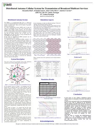
Distributed Antenna Cellular System for Transmission of Broadcast/Multicast Services Alexandra Boal 1 , Armando Soares 1 , João Carlos Silva 1,2 , Américo Correia 1,2 ADETTI 1 , ISCTE, Lisbon, Portugal IT 2 , Lisbon Portugal americo.correia@iscte.pt. Vehicular A. Distributed Antenna System

E N D
Distributed Antenna Cellular System for Transmission of Broadcast/Multicast Services Alexandra Boal1, Armando Soares1, João Carlos Silva1,2, Américo Correia1,2 ADETTI1, ISCTE, Lisbon, Portugal IT2, Lisbon Portugal americo.correia@iscte.pt Vehicular A Distributed Antenna System The MBMS is an unidirectional PtM (Point to Multipoint) service for delivering high bit rate multimedia services to a large number of mobile users. There are two modes of operation: multicast and broadcast. In a radio communication system, MIMO refers to links for which the transmitting end as well as the receiving end is equipped with multiple antenna elements. The idea behind MIMO is that the signals on the transmit antennas at one end and the receive antennas at the other end are “combined” in such a way that the quality (bit-error rate or block error rate BER/BLER) or the data rate (bits/sec) of the communication for each MIMO user will be improved. In this study we integrated the MIMO principles into the distributed antenna cellular systems. It is well-known that, in conventional cellular systems [1, 2], each cell is centered around a Node-B, which may employ a set of antennas. By contrast, in the proposed cellular system, each cell has numerous sets of antennas (distributed antennas), which are distributed within the area covered by a cell and are connected to the Node-B using fiber or cable. In the proposed topology, the distributed antennas (DAs) are connected with a number of signal processing centers, which are referred to as base stations (BSs), using optical fibers or cables. Here we still use the concept of BS, however, it is now just a signal processing center, which may be converted from a conventional BS. The antennas at the BS of the proposed system have no priority in comparison with the other distributed antennas. The BS is responsible for the signal processing of the users within the area, which is covered by the distributed antennas connected with this BS. Simulation Aspects In our simulations, we study two different topologies: Macrocell Topology and Distributed Antenna Topology. The chosen tool to develop the simulator at the system level was JAVA, due to the fact of being a multi-platform technology and independent of any other simulation tool. For the Urban Macrocell Topology, 18 tri-sectorial base stations with a site to site distance of 1000m were considered, and forthe Distributed Antenna Topology, were considered 18 tri-sectorial base stations with a site to site distance of 1000m, and some distributed antennas with a site to site of 250m. The following figure shows the Macrocell and the Distributed Antenna Topologies considered in this study. Figure 6. Average Coverage vs S-CCPCH Ec/Ior, Vehicular A. Figure 7. Average Throughput vs S-CCPCH Ec/Ior, Vehicular A. Figure 2. Macrocell Topology. Figure 3. Distributed Antenna Topology. Table 1 presents some of the parameters used in both simulated scenarios. Pedestrian B System Description The novel concept of the proposed system using distributed antennas can be well described with the aid of Figure 1. Table 1. Urban Macrocell and Distributed Antenna Topologies Parameters Figure 8. Average Coverage vs S-CCPCH Ec/Ior, Pedestrian B. Simulation Results Figure 1. A conceptual cellular system structure with distributed antennas. In the proposed system, of Figure 1, the antennas near the borders may be connected with two or three Node-Bs. In more details, as shown in Figure 1, each of the antennas within the dash-dotted box are connected with Node-B of Cell 1 and Node-B of Cell 2, respectively, while the antennas within the dashed circle at the conner jointing Cells 1, 2 and 3 are all connected with respective Node-B of these cells. In the considered system, for the convenience of analysis, we assume that the cells are shaped as hexagons with the common radius of R. As shown in Figure 1, we assume that any pair of adjacent antennas are separated by a distance of r (in this study we assumed that r=250m and R=1000m). Hence, each antenna is surrounded by numerous distributed antennas located at the layered hexagons. Note that, the structure of Figure 1 is sufficiently general for approximately modeling distributed antenna systems that may have an arbitrary antenna density. This can be done by appropriately changing the radius value of R in Figure 1. In the system of Figure 1, we assume that the DAs only implement the functions of conveying a signal from radio frequency (RF) to baseband or from baseband to RF, in order to make the computation burden at a DA as low as possible. Hence, in our DA are conveyed to the BSs, where the processing is carried out. Simultaneously, all the DAs are also used for transmitting signals from the Node-Bs to the MTs, in order to improve the DL transmission quality. The objectives of DAs in wireless systems include the increase of the system capacity, to decrease the transmission power, to reduce the dependence on the centralized control and to redeem the system capacity spent for system configuration in conventional cellular systems. Figure 9. Average Throughput vs S-CCPCH Ec/Ior, Pedestrian B. Conclusions In this poster we have studied a distributed antenna cellular system for transmission of broadcast and multicast services. From the above presented results, it was demonstrated that high bit rates could be supported by the Distributed Antenna Topology, especially at the cell borders. The use of this topology increased the system capacity, decreased the transmission power, reduced the dependence on the centralized control and offered an almost uniform distribution of capacity throughout all area. The last feature is very important for broadcast/multicast services. As expected the Distributed Antenna Topology is the environment that provides better performance results compared to the macro cell topology the ‘basic’ environment. With this study we conclude that MIMO/Distributed Antenna is a key technology in modern digital communication to provide substantial capacity increments not only for unicast services but also for broadcast/multicast services. Figure 4. CDF Geometry Macro and Distributed Antenna cells (most relevant range of values). Figure 5. BLER vs Tx Power for SISO (1x1), MIMO (2x2) and MIMO (3x3). Acknowledgements This paper is co-funded by the European Commission under the framework of IST-2005 27423 Project, C-MOBILE (Advanced MBMS for the Future Mobile World). Blocking zones (left) and dead zones (right) for UL with SIR=3dB