Download
1 / 48
500 likes | 734 Views
Operational Experience of Thermionic CeB 6 Gun at SCSS/SPring-8. H. Maesaka*, K. Togawa , T. Inagaki, K. Onoe , T. Tanaka, A. Higashiya , H. Baba, H. Matsumoto, H. T anaka, Y. Otake and T. Shintake FLS 2010, SLAC. Outline. Introduction X-ray FEL Project at SPring-8

E N D
Operational Experience of Thermionic CeB6 Gun at SCSS/SPring-8 H. Maesaka*, K. Togawa, T. Inagaki, K. Onoe, T. Tanaka, A. Higashiya, H. Baba, H. Matsumoto, H. Tanaka, Y. Otake and T. Shintake FLS 2010, SLAC
Outline • Introduction • X-ray FEL Project at SPring-8 • SCSS Test Accelerator • Electron gun design • Performance • Emittance measurement • Coherent OTR Search • Operational experience • Summary
X-ray FEL Project at SPring-8 • X-ray wavelength: < 0.1 nm • Self-amplified spontaneous emission (SASE) process • Beam energy: 8 GeV • Key technologies • Low-emittance thermionic electron gun: 0.6p mm mrad • High-gradient C-band accelerator: 35 MV/m • Short-period in-vacuum undulator: lu = 18 mm, K < 2.2 • First XFEL light will be delivered in 2011. XFEL 700m
SCSS Test Accelerator • To check the feasibility of XFEL • Extremeultraviolet (EUV) FEL facility • Wavelength:50 – 60 nm for saturated output • Beam energy: 250 MeV • Electron gun is identical to that of XFEL • Saturated EUV laser light is stably generated. Trend graph of FEL intensity
Thermionic-Gun-based Injector • Simple • Thermionic cathode with heater and high-voltage power source • No laser system • Stable • Stable emission rate • Long life time • But low current and long pulse length • Use fast chopper and velocity bunching • No grid electrode, because it causes emittance degradation. 1ns Cathode B f3mm 1ns, 1A 500kV3ms 1A Collimator(f5mm) Pulse deflector (Stripline electrodes) 238 MHz Pre-buncher cavity 7
Gun Design • Requirements from XFEL • Normalized emittance: < 1 p mm mrad • Beam current: > 1 A • Bunch length: 1 ns(after the chopper) Bunch charge: 1 nC • Voltage: 500 kV (as high as possible) • To reduce space-charge effect • Cathode • CeB6 single crystal • 3mm diameter • ~ > 1400 deg.C for 1A beam • K. Togawa et al., Phys. Rev. ST Accel. Beams 10, 020703 (2007) Thermal Emittance
Cathode Assembly • CeB6 cathode is mounted in a graphite sleeve • Heated to ~ 1400 deg.Cby graphite heater • 500 kV pulse voltage (3ms) is applied to 50 mm gap (10 MV/m) Beam 10MV/m 3mm
High Voltage Power Supply • 50 kV Inverter power supply • Voltage stability: ~10 ppm (rms) • Oil-filled compact pulse modulator • ~ 3 ms pulse • Same as klystron power source • Gun high-voltage tank • Pulse transformer steps up the voltage to 500 kV. • Dummy tube absorbs extra power • Stable impedance and easy cooling Dummy tube AC 420V Pulse forming network ~200A 50kV Inverter power supply Beam 500kV 1:21 1A Thyratron Cathode Pulse transformer Oil-filledcompactpulse modulator Gun high-voltage tank
Normalized Emittance Phase space profile Charge density profile • 0.6 p mm mrad (rms) • Without 10% tail component • Energy: 500 keV • Current: 1 A • Measured by double-slit method
Estimation of Slice Emittance from SASE-FEL Energy Curve • FEL energy curve was compared with simulation Slice emittance of SCSS test accelerator: ~ 0.7 p mm mrad Gun emittance is conserved after x300 bunch compression
Coherent OTR Search Courtesy of K. Togawa Bunch compression ratio was changed by the RF phase of S-band accelerator. SCSS test accelerator Observed point 250MeV Superposition of 5 shots Very stable 1mm OTR Image
OTR Intensity v.s. Bunch Compression Courtesy of K. Togawa • OTR intensity as a function of S-band RF phase. • Compression factor (calculation) is also plotted. SCSS test accelerator 250 MeV ~0.25 nC/bunch Intensity was normalized by charge and g2 Lasing point Total compression factor ~ 300 We didn’t observe non-linear amplification of OTR. The gun emits a temporally and spatially smooth beam.
Operation at the SCSS test accelerator • Cathode heater is always on. • Except for shutdown periods • CeB6 surface is cleaned by evaporation (10nm/hour) • Sometimes cathode temperature is adjusted to keep the emission. (once per three month) • High voltage is turned on at 9:00 and off at 19:00 on weekdays • Fault rate • Less than once per day. • Mainly caused by thyratron misfire. • No spark around the cathode. • Down time due to the gun fault is only 0.4 %.
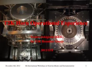
History of the SCSS test accelerator • 2001-2003: Gun R&D • 2004-2005: Construction of the SCSS test accelerator • 2005 Oct.: Started operation • 2006 Jun.: First lasing • 2006 Oct.: Dummy tube trouble • 2007 Oct.: FEL saturation • 2008 Jan.: Cathode replacement after 20,000 hour operation (heating time) • 2010 Aug.: Cathode replacement?
CeB6 cathode after 20,000 hour heating. Courtesy of Shintake-san The cathode surface became concave of 0.2 mm deep from the initial flat surface. It corresponds to evaporation speed of 10 nm/hour ( 10 nm/h x 20,000 h = 200 micron-meter)Concave geometry made beam slightly focusing, but did not break emittance.Electron microscope study showed (1) Surface is fairly smooth, (2) covered by carbon contamination (lowered electron emission).
Future Plan • New gun for XFEL • Identical to the SCSS test accelerator • Delivered soon • High-voltage test will be done in the coming April • Possible R&D areas • More stable power source • Thyratron Solid-state switch • Dummy tube more stable and longer life dummy load • Multi-bunch operation • Done by longer pulse generator for the chopper • Low charge operation with better emittance • Need thin collimatoror thin cathode • Higher current • We can do that with higher cathode temperature. • But cathode life time is shortened. • Higher voltage • Need improvements to prevent the cathode and the insulator from arcing • Higher repetition rate • Cathode itself is OK for kHz order • Depending on the high voltage power supply
Summary • Thermionic gun • CeB6 single crystal • 3mm diameter • ~> 1400 deg.C • 500 kV, 1 A • Low emittance and smooth beam • 0.6 p mm mrad • No coherent OTR No spiky modulation • Operation experience • Stably operated for four years. • Fault rate: less than once per day • Down time: only 0.4 % (2008 – 2009) • Cathode lifetime:~ 20,000 hours (heating time)
Chopper • 1ns bunch is extracted by pulse deflector from 3 ms beam. • No grid electrode chopped 1ns Cathode B f3mm 1ns, 1A 500kV3ms 1A Collimator (f5mm) Pulse deflector (Stripline electrodes) 238 MHz Pre-buncher cavity
Beam Profile and Emittance after the Chopper • Round, flat and smooth beam is generated. • Emittance was measured by slit scan method. • 1.1 p mm mrad(Without 10% tail) • This value can be larger than the true emittancebecause of the space charge effect and the poor resolution of the fluorescent screen Fluorescent screen image Emittance
Longitudinal Bunch Profile Measured by RF Zero Phasing Method Courtesy of K. Togawa Peak Current vs. S-band TWA Phase (Data) (Calculation)
OTR Measurement Setup Courtesy of K. Togawa Transmission of vacuum window Kovar glass Quartz Sapphire Gold target (t~250nm) Sapphire window Wavelen`gth [mm] Sensitivity of CCD camera
2008/01/28 First experience, but team did nice work. We replaced CeB6 crystal in SCSS accelerator, after 20,000 hour heating. Courtesy of Shintake-san Anode flange had color change.
Fault Statistics • Gun faults • Mainly comes from the trip of the high-voltage power supply • Down time is only 0.4 %. • Trip rate: less than once per day
Dummy Tube Trouble • Occurred in Oct. 2006. • Cathode of the dummy tube is shorted to the ground. • Inside of the vacuum vessel. • Insulation of the heater cable was insufficient. • Now, it’s improved.
Choice of Thermionic Electron Source • We chose the thermionic gun followed by chopper and velocity bunching system. • Using the thermionic emitter, the system becomes simple, eliminating use of laser system (for photo-cathode gun), which requires more frequent maintenance than the thermionic cathode gun. • We believe “electron cloud emitted from the thermionic cathode has smooth temporal and spatial distribution. There is no any internal structure”. It is the nature of the thermionic electron emission (statistics). • In the chicane bunch compressor, CSR effect will amplify the density modulation in the incoming electron bunch. Fluctuation of laser beam (fine structure of temporal power profile) might be a source of CSR instability. Quiet electron beam from the thermionic emitter is desirable to cure CSR instability. (need to see X-ray lasing) • Thermionic gun system does not require “the laser heater” to smear the fine structure in the bunch. • For future upgrade, seeding scheme require smooth beam.
Emittance Record in SCSS to XFEL/SPring-8 • 2001~2003 SCSS R&D CeB6 thermionic gun • 2004~2005 SCSS Test Accelerator Construction • 2006 JuneFirst Lasing 49 nm at test accelerator. • 2007 Oct. Saturation at 50~ 60 nm • 2006 April XFEL/SPring-8 Construction was funded. Beam optics design. Technical design.2007 Technical design, contract. • 2008 Mass-production of hardware components. • 2009 March. Linac, Undulator hall building completed. Hardware installation. • 2010 Oct. High power processing 8 GeV accelerator. • 2011 April~ Beam commissioning. First lasing at 1 A. 0.6 p.mm.mrad @ 1 A DC, 500 kV X 300 Compression 0.7 p.mm.mrad @ 300 A, 0.7 psec, 250 MeV, 0.3 nC X 10 Compression 0.8 p.mm.mrad @ 3k A, 8GeV
1 p mm-mrad emittance beam from thermionic cathode was challenge, or crazy? Eliminating control grid from cathode. Smaller size cathode, from 8 mm to 3 mm diameter. Higher gun voltage, 150 kV to 500 kV. Using single crystal CeB6 cathode. this picture is copied from LCLS “Conceptual Design Report”, SLAC-R-593 UC-414
Thermionic Gun looks better. RF-Photocathode gun. Thermionic gun The non-linear space charge field runs with bunch. emittance increases and energy spread increases. Electrons run in static field. Uniform beam linear field no emittance dilution no energy spread Time dependent rf-kick can be cured by solenoid. Fluctuations will be copied from the laser to the electron.
and, we need a quiet beam. • Intensity modulation on laser pulse will be copied on electron density coming out from RF photocathode • It might be a source (seeding) of CSR instability.
Source of Modulation in Photocathode RF-Gun multi-line oscillation in high gain medium Even a small power cause intense modulation, due to heterodyne amplification. • Laser two color mixing THz laser source uses this. This modulation is copied on electron beam and cause CSR instability.
Modulation Transfer • RF-Gun carries modulation wavelength 1 um or longer to downstream, and amplified with CSR and convert into visible light in chicane through “wavelength compression” T. Shintake, "Focal Point Laser Field as Optical Seeder", Proc. FEL2006, Berlin Germany
Use Small Size Cathode…First Strategy for smaller thermal emittance RF photo-cathode injector. Assume ~ 2 mm laser spot size. Same order! Te is “measured” effective electron temperature of copper cathode using 266 nm laser (ref. 2). k Te = 0.27 eV (2360°C). Thermionic cathode Operating Temperature 1500°C Thermal Emittance 3mm diameter cathode (CeB6) is used in a low emittance injector. (SCSS SPring-8/RIKEN)
Graphite Heater 1700 deg. C CeB6 Single Crystal 3 mm diameter Cathode Holder (graphite)forms parallel field four slots provide spring action. 1 A, 10 MV/m, 500 kV SUS316 (clean-Z) Target image of pyro-temp measurement. Edge does not case high voltage break down • 1500 deg.C. Highest temp. in system • Evaporating CeB6 at 1 nm/hour • Self Surface Cleaning • Surface Smoothing • Very stable e-emission • 1 % decay per month • trim heater power each 3-months • Long life ~20,000 hour
Operational Experience of 500 kV Gun Electro-polished SUS SUS316 (clean-Z) • Gun sits inside HV pulse tank, filled with oil. • Applying 500 kV pulse. • 3 micro-sec pulsedriven by klystron modulator. • HV processing is a few hours to reach 500 kV • No HV breakdown at 500 kV for 4 years, daily operation. No baking
Q&A on the CeB6 electron gun • Why don’t we use LaB6? • CeB6 has twice longer lifetime than LaB6. • Can we use needle shape cathode like electron microscope for the FEL? • No. We need Ampere class beam. Available beam current density from CeB6 cathode is < 30 A/cm2. To obtain 1 A, we need at least 2 mm diameter. The current is also space charge limited. • For longer lifetime, it is better to keep cathode temperature lower,and lower current density, thus we use 3 mm diameter cathode. • Can we apply DC voltage on the gun? • No. DC high voltage will cause a large dark current flow from cathode electrode and HV breakdown. • At pulse width shorter than 10 micro-sec, HV breakdown limit becomes a few times higher than DC limit. Thus we use 3 micro-sec, 500 kV pulse driven by pulse power modulator. • Do we need to apply mechanical polish the cathode electrode? • No, polishing with diamond powder causes HV breakdown. Electro polishing is the best choice for stainless steel.
CeB6 Crystal Cathode has reached its lifetime after 20,000 hour operation. January 2008, right after the new year holiday, the emission current decreased quickly by 50%. It has been nicely running for user experiment till end of December 2007, (60 nm full saturation) This crystal was installed in October 2005. Lifetime is 20,000 hours, which is shorter than we expected. But, it is fairly long enough, we decided to regularly change the crystal every year at summer shutdown. To replace cathode and tuning beam to recover full saturated lasing was two-week job.