Download
1 / 21
210 likes | 393 Views
Electrical and Electronic Systems 5.2 – key points. Kirchhoff postulated that in any circuit the sum of currents entering a node or junction equals the sum of the currents leaving that node. The algebraic sum of currents entering and leaving a node is zero

E N D
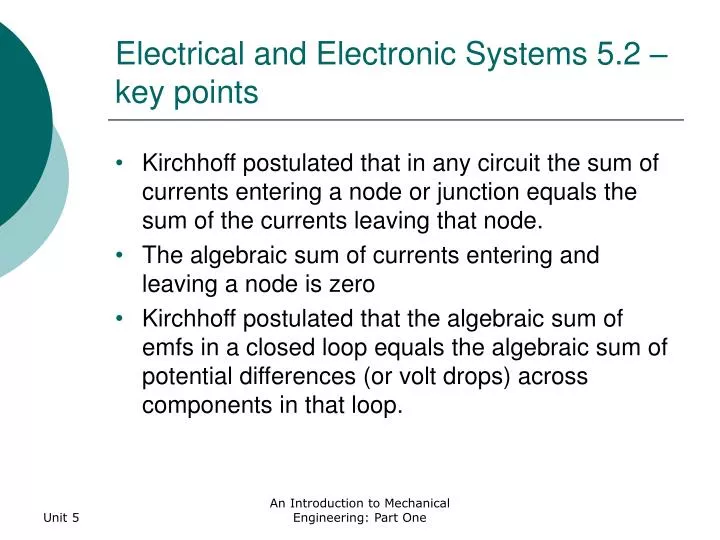
Electrical and Electronic Systems 5.2 – key points • Kirchhoff postulated that in any circuit the sum of currents entering a node or junction equals the sum of the currents leaving that node. • The algebraic sum of currents entering and leaving a node is zero • Kirchhoff postulated that the algebraic sum of emfs in a closed loop equals the algebraic sum of potential differences (or volt drops) across components in that loop. An Introduction to Mechanical Engineering: Part One
Electrical and Electronic Systems 5.2 – key points • The algebraic sum of voltages around a closed loop is zero. An Introduction to Mechanical Engineering: Part One
Electrical and Electronic Systems 5.2Learning summary By the end of this section you will: • be familiar with the constituents of an electric circuit; • understand the concepts of voltage, current and resistance; • be able to distinguish between electromotive force and volt drop; • be capable of using Ohm’s Law to analyse simple circuits; • understand resistivity and be able to calculate the resistance of a conductor; • be able to calculate the equivalent resistances of series and parallel circuits; • understand Kirchhoff’s Current and Voltage Laws; • be capable of using mesh analysis to analyse the current distribution in a circuit; • be able to use a bridge circuit to measure resistance and strain. An Introduction to Mechanical Engineering: Part One
Electrical and Electronic Systems 5.3 – key points • By convention it is assumed that a magnetic field circulates clockwise around a conductor carrying current into the page and anticlockwise around a conductor where the current flows out of the page. This is known as the right hand screw rule. • From his experiments Faraday was able to deduce that the magnitude of the emf, e induced in the coil (as measured by the galvanometer) was proportional to the rate of change of magnetic flux linkages with the coil. An Introduction to Mechanical Engineering: Part One
Electrical and Electronic Systems 5.3 – key points • By convention it is assumed that a magnetic field circulates clockwise around a conductor carrying current into the page and anticlockwise around a conductor where the current flows out of the page. This is known as the right hand screw rule. • From his experiments Faraday was able to deduce that the magnitude of the emf, e induced in the coil (as measured by the galvanometer) was proportional to the rate of change of magnetic flux linkages with the coil. An Introduction to Mechanical Engineering: Part One
Electrical and Electronic Systems 5.3 – key points • The emf induced in a coil is equal to its inductance multiplied by the rate of change of current flowing through it. • Mechanical work done = force on conductor distance moved by the conductor to move the conductor. • Mechanical work done = electrical energy supplied An Introduction to Mechanical Engineering: Part One
Electrical and Electronic Systems 5.3Learning summary By the end of this section you will: • be familiar with the constituents of a magnetic circuit; • understand the concepts of flux, flux density, magnetomotive force (mmf), reluctance, magnetic field strength and permeability; • be able to analyse magnetic field in toroids with both magnetic and non-magnetic cores; • understand the principles of electromagnetic induction; • understand Faraday’s Law; • calculate the current in a direct current circuit with inductance and resistance; • compute the energy stored in an inductor; • analyse the force on a current carrying conductor in a magnetic field; • analyse systems with magnetic and non-magnetic elements in series; • calculate magnetic fields in systems with parallel paths. An Introduction to Mechanical Engineering: Part One
Electrical and Electronic Systems 5.4 – key points • The movement of electrons produces a current, which by convention flows in the opposite direction to the electrons. This current, i equals the rate at which charge, q moves through the circuit. An Introduction to Mechanical Engineering: Part One
Electrical and Electronic Systems 5.4Learning summary By the end of this section you will: • understand the concepts of charge, permittivity and capacitance • be able to calculate capacitance • be able to compute the equivalent capacitance of capacitors in parallel, series and combinations thereof • calculate the voltage across a capacitor in a direct current circuit with capacitance and resistance • understand the concept of the time constant of a circuit • compute the stored energy in a capacitor. An Introduction to Mechanical Engineering: Part One
Electrical and Electronic Systems 5.5 – key points • The j operator is linked to the inductive reactance, XLto ensure that both the magnitude and the phase angle of the current are calculated simultaneously. An Introduction to Mechanical Engineering: Part One
Electrical and Electronic Systems 5.5Learning summary By the end of this section you will: • understand how sinusoidal voltages are induced in an alternating current generator; • understand what is meant by root mean square (rms) currents and voltages; • be familiar with the concept of a phasor; • understand the meaning of inductive and capacitive reactance; • be able to calculate the magnitude and phase angle of a current in a circuit that is wholly resistive, inductive or capacitive; • understand what is meant by lagging and leading currents; • be able to calculate the magnitude and phase angle of a current in a circuit comprising at least two different types of component; • know how to convert between Cartesian and polar coordinates; • be able to draw a phasor diagram for a circuit comprising at least two components; • be able to calculate the power dissipation in an alternating current circuit. An Introduction to Mechanical Engineering: Part One
Electrical and Electronic Systems 5.6Learning summary By the end of this section you will: • know how three phase voltages are generated; • remember that in a balanced supply the voltages are of equal magnitude and are mutually 120o apart; • be able to distinguish between star and delta connections; • be able to differentiate between phase and line currents and voltages; • remember that in star connection line voltage equals √3 phase voltage and line current equals phase current; • remember that in delta connection line voltage equals phase voltage and line current equals √3 phase current; • be able to analyse star and delta connected systems; • be able to draw a phasor diagram for a three phase network; • calculate the power dissipated in a three phase load; • remember that with the same supply voltage and same load impedance, the power dissipated in a delta connected load is three times larger than in a star load. An Introduction to Mechanical Engineering: Part One
Electrical and Electronic Systems 5.7Learning summary By the end of this section you will: • know how a junction diode works; • be able to distinguish between half and full wave rectifiers and controlled and uncontrolled rectifiers; • recognize the output waveforms for each of these rectifiers; • be able to calculate the average dc output voltage for these rectifiers; • understand the principles of voltage smoothing; • be able to calculate the average dc output voltage and ripple voltage from a smoothed supply; • know how a zener diode works; • understand the principles of operation of a voltage stabilizer; • be able to calculate the average dc output voltage from a stabilized supply. An Introduction to Mechanical Engineering: Part One
Electrical and Electronic Systems 5.8Learning summary By the end of this section you will be able to analyse and design: • a simple transistor amplifier; • a inverting amplifier; • a summing amplifier; • a non-inverting amplifier; • an integrating amplifier. An Introduction to Mechanical Engineering: Part One
Electrical and Electronic Systems 5.9 – key points • Any system in which the state of all points must be either 0 or 1 is known as a binary system. • The bar over the Ain the Boolean expression for the NOT gate indicates inversion, i.e. equals NOT A. An Introduction to Mechanical Engineering: Part One
Electrical and Electronic Systems 5.9Learning summary By the end of this section you will: • be familiar with the operation of common combinational logic gates; • have an understanding of Boolean algebra; • be able to derive the truth table, Karnaugh map and Boolean expression for the output of a combinational logic circuit; • be able to design a combinational logic circuit; • understand binary notation; • be familiar with the operation of bistables; • be able to derive the state table for a sequential logic circuit; • be able to analyse the operation of a digital to analogue converter; • understand how an analogue-to-digital converter works An Introduction to Mechanical Engineering: Part One
Electrical and Electronic Systems 5.10 – key points • The ratio of primary turns to secondary turns is called the ‘turns ratio’ or ‘transformation ratio’. An Introduction to Mechanical Engineering: Part One
Electrical and Electronic Systems 5.10Learning summary By the end of this section you will: • understand how transformers work; • be able to use the turns ratio to calculate the primary or secondary voltage; • be familiar with the concept of magnetomotive force (mmf) balance; • be able to use the mmf balance to find the primary or secondary current; • know how to compute the equivalent impedance of a transformer with a load; • be able to use the voltampere (VA) rating to find the full load primary and secondary currents; • know how to calculate the I2 R losses; • remember that the core losses are constant; • be able to compute the efficiency. An Introduction to Mechanical Engineering: Part One
Electrical and Electronic Systems 5.11 – key points • The speed at which the field rotates is called the synchronous speed, ns. Measured in revolutions per second it is equal to the frequency of the stator currents, f, in hertz (Hz). • The rotor will continue to accelerate until the electrical torque produced exactly equals the mechanical load torque on the shaft. At this point the rotor will be running at a speed, n,slightly slower than the synchronous speed, ns; i.e. at a speed slightly slower than that of the rotating magnetic field. This difference in speed is expressed as a ratio and is known as the slip or per unit slip, s An Introduction to Mechanical Engineering: Part One
Electrical and Electronic Systems 5.11 – key points • The small difference between the speed of the rotating field and that of the rotor is fundamental to the operation of the induction motor. An Introduction to Mechanical Engineering: Part One
Electrical and Electronic Systems 5.11Learning summary By the end of this section you will: • understand how three-phase induction motors work; • comprehend the concept of slip and how it relates to rotor speed; • understand how the ratio of rotor resistance to rotor standstill reactance affects the torque-slip characteristics; • comprehend how the torque-slip characteristic may be modified by fitting two rotor windings; • understand how the number of magnetic poles affects the synchronous speed and rotor speed; • calculate the driving torque; • compute the starting torque; • calculate the mechanical output power An Introduction to Mechanical Engineering: Part One


![SUBELEMENT T5 [4 Exam Questions - 4 Groups]](https://cdn0.slideserve.com/1420383/subelement-t5-4-exam-questions-4-groups-dt.jpg)