Download
1 / 37
370 likes | 568 Views
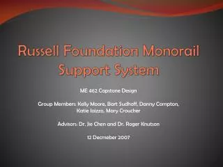
Russell Foundation Monorail Support System. ME 462 Capstone Design Group Members: Kelly Moore, Bart Sudhoff, Danny Compton, Katie Iaizzo, Mary Croucher Advisors: Dr. Jie Chen and Dr. Roger Knutson 12 Decmeber 2007. Introduction. Background Design Objectives Material Selection

E N D
Russell Foundation Monorail Support System ME 462 Capstone Design Group Members: Kelly Moore, Bart Sudhoff, Danny Compton, Katie Iaizzo, Mary Croucher Advisors: Dr. Jie Chen and Dr. Roger Knutson 12 Decmeber 2007
Introduction • Background • Design Objectives • Material Selection • Cost Evaluation • Concept Design • Product Evaluation • Conclusion • Recommendations • Answer Questions
Russell Foundation • Founded By Bishop Michael Russell and his Father In 2003 • Faith Based Community Development Organization • Renders Self-sufficiency Programs to Help Stabilize Families and Communities • Provides Jobs for Local Communities • Environmentally Friendly Initiatives
Reasons For Design • Reduce Traffic Congestion around Chicago-Indiana Area • Provide High Speed Transportation • Create Jobs in Indiana • Pioneering Environmentally Friendly Mass Transit Solutions
Customer Requirements • Travel 75 MPH • Support Renewable Energy Source • Easy Assembly • Easy Maintenance • Smooth Rail Transition • Appearance • Support 160,000 lb load • Minimize Stopping Time • Minimize Cost • Minimize Environmental Effects
Engineering Requirements • Minimize Resistance (Rail) • Maximize Allowable Stress (Structure) • Equipment Hours • Labor Hours • Minimize Rail Height Difference • Public Appearance Rating • Maximize Allowable Stress (Rail) • Maximize Allowable Stopping Force • Minimize Cost • Minimize Environmental Effects on Material
Column Support Box beam Concrete base Bolted to cross-support
Cross Support Box beam Bolted to column Supports rails
Standard I-Beam W27 x 368 Standard Size Internal height equal to 25.43 inches Fits standard 22 inch tire diameter
Column Support Assembly All parts bolted and welded
Types of Steel • Two common types used: ASTM A992 and ASTM 588 • More common steel types reduce cost • High strength, low alloy steel, which used recycled metals • Saves on cost of manufacturing • Environmentally friendly
Price Comparison • Consider long term maintenance and repair cost • Northwestern University experiment • A992 corrodes 64% more over time than A588 • A992 would last less than half as long as A588 (weathering steel)
Loading (Structure) • Deadweight Load • 80,000 lbs (355868 N) per Rail • Braking Force • 9.8 m/s2 * 80,000 lbs • Fixed Supports • Base – Ground Interface • Open End Rails
Equivalent Stress (Structure) • Maximum • 5.53e7 Pa
Shear Stress (Structure) • Maximum • 2.81 e7 Pa
Total Deformation (Structure) • Maximum • 16.75 mm • Location • Mid-span
Factor of Safety (Structure) • Minimum • 6.15 • Location • Beam- Near Connection
Loading (Beam) • Deadweight load • 40,000 lbs per Flange • Fixed Supports • Open Ends of Beam
Total Deformation (Beam) • Maximum • 9.5 mm
Fatigue Life (Beam) • Minimum • 8.03e5 cycles
Concluding Remarks • Our designed is based on the customer requirements and goals of the Russell Foundation. • The factor of safety meets required limit of 5-7 • Fatigue life exceeded 8.0 e5 cycles • A588 steel resists weathering without excessive cost • Single column design minimizes footprint • Designed to easily integrate renewable energy sources
Structure Span Length • Preliminary Testing • Larger Beam • 39 in. Interior Beam height • Factor of Safety Increased to 9.53 • Custom Beam • Standard Size Not Available
References http://www.uspto.gov/patft/index.html http://www.delphion.com/home Project definition packet, Russell Foundation “IndianaFreight and IndianaMonorail,” Roger Knutson; Russell Foundation; Advance Transit Solutions, LLC, May 2007 http://www.wisegeek.com/what-is-a-steel-i-beam.htm http://en.wikipedia.org/wiki/I-beam Machinist’s Handbook 12th Edition, Lang, page 397 http://www.matweb.com