Download
1 / 24
240 likes | 343 Views
Boolean Algebra – the ‘Lingua Franca’ of the Digital World

E N D
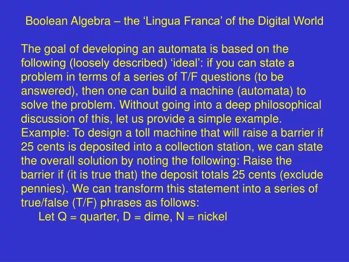
Boolean Algebra – the ‘Lingua Franca’ of the Digital World • The goal of developing an automata is based on the following (loosely described) ‘ideal’: if you can state a problem in terms of a series of T/F questions (to be answered), then one can build a machine (automata) to solve the problem. Without going into a deep philosophical discussion of this, let us provide a simple example. • Example: To design a toll machine that will raise a barrier if 25 cents is deposited into a collection station, we can state the overall solution by noting the following: Raise the barrier if (it is true that) the deposit totals 25 cents (exclude pennies). We can transform this statement into a series of true/false (T/F) phrases as follows: • Let Q = quarter, D = dime, N = nickel
Raise the barrier if the deposit equals • Q or (2D and N) or (3N and D) or (5N) Each phrase (e.g., 2D and N) can be checked as to its truth or falsity. Hence, we can build a machine to solve this problem because it is a problem involving T/F statements.
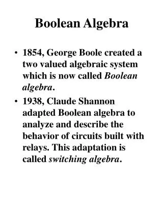
Boolean algebra underlies the manipulation of logical statements involving truth or falsity. There are three boolean operations that support logic: and or not (In fact, we only require two of these, either (and, not) or (or, not) – but we will use all three for the moment.) The general form of a logical statement: (phrase) logical operator (phrase) Each phrase can also have this format, leading to compound statements as exemplified by the example noted above. The linguistic elements of such statements are called (logical) variables or “literals.” A phrase usually includes one or more linguistic variables. The following table summarizes the logical operations.
Operation example notation symbol And c = A and B and Or c = A or B or + Not c = not A A A’ Logical operations are defined by means of a TruthTable.
and operation Truth Table: • A B C = A B • 0 0 0 • 0 1 0 • 1 0 0 • 1 1 1 • In words: A and B is true (T or 1) if both A and B are both true, else the result is false (F or 0). • (inclusive) or operation Truth Table: • A B C = A + B • 0 0 0 • 0 1 1 • 1 0 1 • 1 1 1
In words: A or B is true (1) if either A or B or both are true, else the result is false (0). • not operation Truth Table (unary operator): • A C = not A (= A’) • 0 1 • 1 0 • In words: The not operation inverts or reverses the sense of the defining literal. If the literal is true (1), the result is false (0) and if the literal is false (0), the result is true (1). • A Truth Table specifies the functional relation between literals.
Example: A physician looks for three symptoms from a patient in order to make a diagnosis. She decides on a particular diagnosis if any two or more of the three symptoms are expressed. Let’s develop a Truth Table for the diagnosis and design a machine that automatically makes such a diagnosis. (Let Sx = 1 mean that symptom ‘x’ is present.) • S1 S2 S3 Diagnosis (D) • 0 0 0 0 • 1 0 0 0 • 0 1 0 0 • 1 1 0 1 • 0 0 1 0 • 1 0 1 1 • 0 1 1 1 • 1 1 1 1 • We can write an equivalent logic equation for this:
D = S1S2S3 + S1S2S3 + S1S2S3 + S1S2S3 and the machine that automatically determines the diagnosis is: S1 S2 S3 Is there another way to design this automata?
Suppose these symptoms change with time. What would the machine indicate? • S1 • S2 • S3 • D • time 1 0 Boolean algebra An algebra that deals with binary variables and logical operations. Boolean identities X + 0 = X X1 = X X + 1 = 1 X0 = 0
X + X = X XX = X • X + X = 1 XX = 0 • X = X • 0 = false; the null or empty set • 1 = true; the universal set • Can I establish the logical certainty of these identities? Yes. To do so, use a Truth Table; create columns in the TT for both sides of the identity and if they are the same (equal) for each condition of the defining variables, then the two sides of the equation are equal and the identity is established as shown below for the identity X + X’ = 1 • ? • X X’ X + X’ = 1 • 0 1 1 1 • 1 0 1 1
Since the columns enclosed within the rectangles are equal for all possible values of the defining variable X – X can only take two values, 0 or 1 – the proof of the identity is demonstrated. • A most important identity is called DeMorgan’s Law (or DeMorgan’s Theorem). It has two forms; these forms are duals of each other. • X + Y = X Y • X Y = X + Y • This can be extended to any number of variables (e.g., X, Y, Z, …). • N.B.B. (Note extremely well!!) XY XY • We can use the identities to simplify logical functions thereby simplifying the automata implementing those ftns.
Example: Simplify X’ Y’ + X’ Y + X Y = X’ (Y + Y’) + X Y (Distributive property) = X’ + X Y because Y + Y’ = 1 and X’ 1 = X’ Can we make this simpler? Note that X’Y = X’ Y + X’ Y (adding the same term does not alter the logical outcome). Now, substitute this into the original equation (X’Y’+X’Y+XY) to yield (X’Y + X’Y’) + (X’Y + XY) = X’ (Y+Y’) + Y(X’ + X) = X’ + Y which is simpler than the first result. It is sometimes difficult to reduce expressions using “observations” as we just did.
There are formal methods to “minimize” logic ftns. We study one method called Karnaugh Maps (KMs). Before we do so, we examine two shorthand (notation) methods for representing Truth Tables: Sum of products, Product of sums. Let’s look at a 3-variable TT and write the Boolean expressions that make each row logically true. In addition, we add an equivalent expression using DeMorgan’s Law. Dec. No. X Y Z TRUTH DEMORGAN (TRUTH’) 0 0 0 0 X’Y’Z’ (X+Y+Z) 1 0 0 1 X’Y’Z (X+Y+Z’) 2 0 1 0 X’Y’Z (X+Y+Z’) 3 0 1 1 X’YZ (X+Y’+Z’) 4 1 0 0 XY’Z’ (X’+Y+Z) 5 1 0 1 XY’Z (X’+Y+Z’) 6 1 1 0 XYZ’ (X’+Y’+Z) 7 1 1 1 XYZ (X’+Y’+Z’)
Now, if we were given a ftn such as • F = X’Y’Z’ + X’YZ’ + XY’Z + XYZ • We could represent this ftn in shorthand as: • F = (0,2,5,7) • or alternatively as • F =(1,3,4,6) = (X+Y+Z’)(X+Y’+Z’)(X’+Y+Z)(X’+Y’+Z) • Why is this latter representation correct? • X Y Z F F’ • 0 0 0 1 0 • 0 0 1 0 1 • 0 1 0 1 0 • 0 1 1 0 1 • 1 0 0 0 1 • 1 0 1 1 0 • 1 1 0 0 1 • 1 1 1 1 0 • Now, working with F’ as • F’ = (1,3,4,6)=X’Y’Z+X’YZ+XY’Z’+XYZ’ • and F = F’’ is obtained using DeMorgan’s Law:
F = (X+Y+Z’)(X+Y’+Z’)(X’+Y+Z)(X’+Y’+Z) which can be written as a “product of sums” where the underlying (equivalent) decimal numbers are included as a sum of the complement of the equivalent binary bits. F = (1,3,4,6) Consider, as an example, the term generated by the first decimal number (1). This decimal number has 001 as its equivalent binary value; X=0, Y=0, Z=1. The term in the product sequence would then be (X+Y+Z’). Notice that we included the complement of the X, Y, and Z terms making up the digit. The other terms would have similar arrangements and would be combined as products (“and”). There are thus two forms of machine (gate arrangements) that can implement this logical ftn.
0 1 3 2 4 5 7 6 The numbers in the gates refer to the terms and inputs that would be connected to the particular gate. For example the gate marked with a “7” would have X, Y, Z as inputs while the gate marked with a “5” would have X, Y’, and Z as inputs. On the OR gates, you must remember to provide complements of the variables. For example, the gate marked “6” would include X’, Y’ and Z (rather than X, Y,
and Z’ which is the binary equivalent of the decimal number 6). Karnaugh Maps (KMs) This is a graphical representation of a logic ftn. and supports a technique for reducing the logic ftn. to its essential terms. A KM to depict possible outcomes for a 3-variable function looks like the following: Y X YZ 00 01 11 10 0 0 1 3 2 X 1 4 5 7 6 Z The numbers in each cell represent the decimal equivalents
of the binary outcomes for that cell. For example, the cell where X=1, Y=1, and Z=1 contains the decimal number 7. Let’s consider the KM for the following logic ftn. as depicted in a TT. X Y Z F Decimal Equivalent 0 0 0 0 0 0 0 1 0 1 0 1 0 1 2 0 1 1 1 3 1 0 0 1 4 1 0 1 1 5 1 1 0 0 6 1 1 1 0 7 The KM representation of this ftn is given below:
Y X YZ 00 01 11 10 0 0 0 1 1 X 1 1 1 0 0 Z How do KMs help us to minimize logic ftns.? The key lies in the fact that cells in KMs are ‘adjacent’ to each other. Adjacency means that cells next to each other differ in only one bit position.
00 01 11 10 X1 0 1 X2 Consider the cells marked as “x1” and “X2”. Their binary values are: X1 = 0 1 0 X2 = 1 1 0 Notice they only differ in the 1st bit position. Suppose now that we had to implement an array of gates to create the following logic ftn. F = X’YZ’ + XYZ’ (20.1)
We could minimize this ftn by using the Boolean distributive rule: F = YZ’ (X’ + X) = YZ’(1) = YZ’ For simple ftns like this we can apply the rules of Boolean algebra directly. More complex ftns. may not be easily reduced by direct application of the basic identities of Boolean algebra. Consider the following ftn. F = X’Y’Z + XYZ + XY’Z + X’YZ (21.1) This actually reduces to F = Z but this is not so obvious when you start the reduction. Using KMs the result we demonstrate is ‘obvious’. KM Reduction When two adjacent cells of a KM are occupied by logical 1s, it means that one of the defining variables is redundant.
Consider the example (20.1) noted above. 00 01 11 10 0 1 1 1 If we use YZ’ to represent these cells then it ‘does not matter’ what value we assign to X (i.e., X or X’) since both cells are 1 when F = YZ’. In other words, X is redundant because these cells are adjacent to each other. If we consider the more complex example (21.1), its KM is:
00 01 11 10 0 1 1 1 1 1 All four of the required cells of the logic ftn. are ‘covered’ for F = Z. For each increment of two adjacencies one additional variable becomes redundant. However, only groups of 2,4, 18, 16, … are possible. For example, consider the following map: 1 1 1 1 1 1
All six cells cannot be represented (‘covered’) by one term. Instead, we must cover the map using two groups of 4 cells. 00 01 11 10 0 1 1 1 1 1 1 1 In addition, it is very important to be aware that cells at the corners are also adjacent: