Download
1 / 64
750 likes | 1.13k Views
MB Booting and ASUS ASIC. Dec. 20, 2002 CSC / ASUS. AGENDA. 1. ACPI states and MB Bootup. 2. Determination of CPU Vcore, CPU Core Frequency, CPU Frequency Multiplier. 3. Wake on LAN, Wake by KB, Wake On Ring, Wake On USB, AC Power Loss Restart.

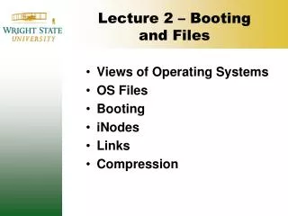
E N D
MB Booting and ASUS ASIC Dec. 20, 2002 CSC / ASUS
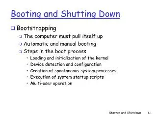
AGENDA 1. ACPI states and MB Bootup. 2. Determination of CPU Vcore, CPU Core Frequency, CPU Frequency Multiplier. 3. Wake on LAN, Wake by KB, Wake On Ring, Wake On USB, AC Power Loss Restart. 4. Dual CPU Support Celeron FC-PGA Coppermine 5. POST
ACPI States • What is ACPI ? • Advanced Configuration and Power Interface • ACPI • ACPI evolves the existing collection of power management BIOS code, APM APIs, PNPBIOS APIs, and so on into a well-specified power management and configuration mechanism. It provides support for an orderly transition from existing (legacy) hardware to ACPI hardware, and it allows for both mechanisms to exist in a single machine and be used as needed. • Further, new system architectures are being built that stretch the limits of current Plug and Play interfaces. • ACPI evolves the existing motherboard configuration interfaces to support these advanced architectures in a more robust, and potentially more efficient manner.
G3 Mechanical Off BIOS Routine Legacy G0 (S0) Working Wake Events G2 (S5) Soft Off S4 S3 S2 G1 Sleeping S1 ACPI States Global System States 1. G3 - Mechanical Off State ATX Unpluged Battery Power Only 2. G2 / S5 - Soft Off ATX pluged +5V Standby and Battery 3. G1 - Global Sleeping State S1 : No system context is lost S2 : Cache context is lost S3 : CPU, cache, and chipset context is lost. Memory is maintained. Suspend To RAM (STR) S4 : system context is maintained in Non-volatile storage. Suspend To Disk (STD) 4. G0 - Global Working State Full running CPU States C0 , C1 , C2 , C3
Global System States 3. G1 - Global Sleeping State S1 : No system context is lost , S2 : Cache context is lost S3 : Suspend To RAM (STR) , S4 : Suspend To Disk (STD) 4. G0 - Global Working State 1. G3 - Mechanical Off State ATX Unpluged , Battery Power Only 2. G2 / S5 - Soft Off ATX pluged , +5V Standby and Battery
Global System States S4 : Suspend To Disk (STD) • System context is maintained on the disk. • All power is shut off, except for the circuits to restart • Externally appears same as S5, but may have different wake events. G2/S5 - Soft Off S5 : Soft Off • System context is not maintained. • All power is shut off except for the circuits to restart. • A full boot is required when waking. G3 - Mechanical Off • All power is shut off except for RTC. • No wake events are possible. G0 - Global Working State G1 - Global Sleeping State S1 : No system context is lost • the STPCLK# signal goes active to the processor. • CPU performs a Stop-Grant cycle. • Cache coherency is maintained. S2 : Cache context is lost • Not supported by ICH S3 : Suspend To RAM (STR) • System context is maintained in system memory. • All clocks stop except RTC clock. • Power is shut off to non-critical circuits. Memory is retained, and refreshes of DRAM continues.
Wake By RTC Wake On USB AC Power Loss Restart Wake On LAN Wake On Ring Wake by PS/2 KB South Bridge (ICH, PIIX4) Power Button ASUS ASIC (97127,99127) ATX Power Supply +3V • 5V • 12V MB Bootup
PS-ON# ATX Power Supply Wake Up Events WOL,WOR, Wake by KB, AC Power Loss Restart PS-ON is an active low signal that turns on all of the main power rails including 3.3V, 5V, -5V, 12V, and -12V power rails. When this signal is held high by the PC board or left open circuited, outputs of the power rails should not deliver current and should be held at a zero potential with respect to ground. Power should only be delivered to the rails if the PS-ON signal is held at ground potential. This signal should be held at +5VDC by a pull-up resistor internal to the power supply. South Bridge (ICH, PIIX4) Power Button ASUS ASIC (97127,99127) ATX Power Supply +3V • 5V • 12V
PS-ON# ATX Power Supply Wake Up Events WOL,WOR, Wake by KB, AC Power Loss Restart 5VSBis a standby voltage that may be used to power circuits that require power input during the powered down state of the power rails. The 5Vsb pin should deliver 5V at a minimum of 10mA for PC board circuits to operate. Conversely, PC boards should draw no more than 10mA maximum from this pin unless a power supply with higher current capabilities is clearly specified. This power may be used to operate circuits such as soft power control. For future implementation it is recommended that the 5Vsb line be capable of delivering 720mA. This increased current will be needed for future implementations with features such as <Wake on LAN>. South Bridge (ICH, PIIX4) Power Button ASUS ASIC (97127,99127) ATX Power Supply +3V • 5V • 12V
AC97 CODEC PCI-ISA Bridge ATX PWR AUX A M R I S A S L O T P C I S L O T S A G P P R O S L O T 820 MCH Socket 370 MTH DIMM SKTs LPC ICH ICH FWH ASUS ASIC IDE CONNs BATT FDD CONN Lithium Battery Output : +3V
Motherboard in G3 Mechanical Off State • When the motherboard is not connected to ATX power, there is only BATT(battery) power on board. • ACPI G3 mechanical state. • There are still certain circuits on the board consuming the BATT power. • ICH • ASIC • other small discrete components. AC97 CODEC PCI-ISA Bridge ATX PWR AUX A M R I S A S L O T P C I S L O T S A G P P R O S L O T 820 MCH Socket 370 MTH DIMM LPC ICH ICH FWH ASUS ASIC IDE 有電 BATT FDD Functions in G3 state being maintained on board by the BATT power are : • CMOS SRAM (in ICH) • RTC ( Real Time Clock ) (in ICH) • AC Power Loss Restart (in ICH) • New CPU Detection (On board) • Chassis Intrusion (On board)
AC97 CODEC PCI-ISA Bridge ATX PWR AUX A M R I S A S L O T P C I S L O T S A G P P R O S L O T 820 MCH Socket 370 MTH DIMM LPC ICH ICH FWH ASUS ASIC IDE BATT FDD Motherboard in G2 / S5 Soft Off State 有電 Two Power planes : 1. BATT 2. Standby Power A.C. Voltage Regulator +3VSB Supply to circuits for Wake Up Event : WOR, WOL, Wake Up by KB, USB Voltage Regulator +1.8VSB Voltage Regulator +3VAux
Motherboard in G2 / S5 Soft Off State 150 Ohm Regulator +5VSB +3VAUX 有電
2. Determination ofCPU Vcore, CPU Core Frequency, CPU Frequency Multiplier.
HIP 6019BCB Bridge Switching Regulator CPU Vcore ASIC CPU Vcore • Klamath PII Later • 5 pins on the CPU to inform the motherboard what sort of core voltage it needs. • VID0 • VID1 • VID2 • VID3 • VID4 • The VID pins on the CPU are not output signals : • Internally connected to GND -- Low • Open circuit -- High +5V CPU 1K 10K VID4 VID3 VID2 VID1 VID0 CPU Internal Ground Vss
PLL Frequency Multiplier Frequency Input fin (VCO) Voltage Controlled Oscillator Frequency Output Phase Detector Loop Filter fout fref Divided-by-N Counter fout / N CPU Core Frequency • PLL • Phase Lock Loop (鎖相迴路 ) • fin = FSB frequency N= Frequency multiplier setting • fout = CPU Internal frequency = N * fin • fout = N * fin
PLL Frequency Multiplier Frequency Input (VCO) Voltage Controlled Oscillator Frequency Output Phase Detector Loop Filter fin fout fref Divided-by-N Counter fout / N CPU FSB Frequency • fin = FSB (Front Side Bus) frequency N= Frequency Multiplier setting • fout = CPU Internal Core Frequency = N * fin C P U CPU Core frequency FS0 Clock Generator PLL FS1 FSB FS2 FS3 Internal N Freq.Multiplier
BF3 +5V +5V +5V +5V BF2 BF1 BF0 Gnd PLL Frequency Multiplier Frequency Input FS0 (VCO) Voltage Controlled Oscillator Frequency Output Phase Detector Loop Filter FS1 fin FS2 fout FS3 fref Divided-by-N Counter fout / N CPU Frequency Multiplier • Klamath PII • Freq. Multiple can be configured by jumpers. • Deschute PII , PIII, and Mendocino Celeron • Freq. Multiple setting is internally locked. • Engineering Sample • Freq. Multiple still can be configured. C P U CPU Core frequency Clock Generator PLL FSB 1 CF4 2 A20M# 3 IGNNE# LINT0/INTR CF3 LINT1/NMI CF2 CF1
Bridge Clock Generator Jumper Settings FS [0:4] FSB ASIC Bridge CPU Freq. Multiplier Jumper Settings BF [0:4] CPU Core FReq ASIC
1 SDOUT 2 SAFE MODE +3V 3 SAFE Mode Setting ICH Register FREQ_STRAP AC_SDOUT
SAFE Mode Setting • [ BF 0,1,2,3 ] = [ H, H, H, H] ===> X 2
Functions activated in G3 state • Functions in G3 state being maintained on board by the BATT power are : • CMOS SRAM (in ICH) • RTC ( Real Time Clock ) (in ICH) • AC Power Loss Restart (in ICH) • New CPU Detection (On board) • Chassis Intrusion (On board)
M146818 CMOS CMOS • Motorola 146818 RTC chip • 256-Byte CMOS Memory (SRAM) powered by BATT • PIIX4 allows the short-ckt of BATT to clear CMOS. • ICH prefers the RTCRST# to clear CMOS • CMOS • POST = Power On Self Test CPU Post Code C5 Copy the BIOS from Flash ROM into E000-FFFF shadow DRAM so that POST will go faster BATT Post Code 0B Read CMOS Data into BIOS Stack Area ICH RTCRST# CLRTC GO ON the POST procedure +3VSB BATT Lithium Battery
S370 CPU CPUPRES# CPU Presence Detection • Slot-1 CPU • SLOTOCC# = Slot Occupation • S370 CPU • CPUPRES# = CPU Presence • This function is powered by Lithium battery • BATT • Still working in G3 state • Any action of removing the CPU • will cause the BIOS to configure CPU again while the system boots up again • CPU speed BATT 99127 VID [0:4] Slot-1 CPU Pin 61 SLOTOCC# SLOTOCC#
CPU Presence Detection • ASUS ASIC 97127 D-Type Flip Flop
Chassis Intrusion +3VAUX ICH Chassis# GPIO 10 BATT +5VSB 1 Chassis 2 ASIC 3 Pin 64 Intrusion
+3VAUX ICH Chassis# GPIO 10 BATT +5VSB 1 Chassis 2 ASIC 3 Pin 64 Intrusion Chassis Intrusion
3. Wake On LAN Wake On Ring Wake Up By KB Wake On USB AC Power Loss Restart
POWER UP CONTROL • BIOS Setup \ Power \ Power Up Control • AC Power Loss Restart • PWR Up On external Modem Act • Wake On LAN or PCI Modem card • Wake On PS/2 KB / PS2 Mouse • Wake Up By Keyboard • Wake On USB Device • Automatic Power Up • CUC2000, CUWE-FX • P3B-F, P3WE
ACPI signaling of ICH • The ICH directly supports different sleep states (S1-S5), which are entered by setting the SLP_EN bit, or due to a Power Button Override. • Sleep states are initiated by • Setting the desired type in the SLP_TYP field and setting the SLP_EN bit.
S0 S0 S0 STPCLK# S1 S3 SLP_S3# SLP_S5# S4/S5 ACPI signaling of ICH ICH STPCLK# SLP_S3# SLP_S5#
S0 S0 S0 STPCLK# S1 ICH S3 SLP_S3# Power Button ASUS ASIC (99127) SLP_S5# S4/S5 ATX Power Supply +3V • 5V • 12V SLP_S3# SLP_S5# PS-ON# ACPI signaling of ICH ICH STPCLK# (SUSA#) SLP_S3# (SUSB#) SLP_S5# (SUSC#) (SUSA,B,C# are forPIIX4)
ICH NAND Gate Power Button A B Y 0 0 1 ASUS ASIC (99127) 0 1 1 1 0 1 1 1 0 ATX Power Supply +3V • 5V • 12V SLP_S3# SLP_S5# PS-ON# ACPI signaling of ICH For ASUS 99127 , the power ON is controlled by PWRBTN# and SLP_S3# . ASUS 97127 SLP_S5# (ICH) 1 0 1 N-Type MOSFET 1
Setting of AC Power Loss Restart Previous Disabled Enabled OFF OFF ON ON OFF ON ONOFF ONOFF ON ON ONOFF ON ONOFF ONOFF ON ON ONOFF ON ONOFF ONOFF ON ON ONOFF ON AC Power Loss Restart • AC Power Loss 1. The AC power cord was unplugged from the ATX power supply 2. The AC power was lost • AC Power Loss Restart • the AC Power is back • +5V standby and the resulting standby power is back • determine if the system would be back to original S0 state or stay in S5 state BIOS setting State of AC Power Loss WOL WOR Disable Disable S5 ( Soft Off ) Disable Disable S0 (Working) Disable Enable S5 ( Soft Off ) Disable Enable S0 (Working) Enable Disable S5 ( Soft Off ) Enable Disable S0 (Working) Enable Enable S5 ( Soft Off ) Enable Enable S0 (Working)
BIOS setting State of AC Power Loss Setting of AC Power Loss Restart WOL WOR Previous Disabled Enabled Disable Disable S5 ( Soft Off ) OFF OFF ON Disable Disable S0 (Working) ON OFF ON Disable Enable S5 ( Soft Off ) ONOFF ONOFF ON Disable Enable S0 (Working) ON ONOFF ON Enable Disable S5 ( Soft Off ) ONOFF ONOFF ON Enable Disable S0 (Working) ON ONOFF ON Enable Enable S5 ( Soft Off ) ONOFF ONOFF ON Enable Enable S0 (Working) ON ONOFF ON ICH : AfterG3_En bit • ON • Return to S0 • OFF • Remain in S5 • ON OFF • CPU is turned on for a while to configure the wake-up circuits of WOL, WOR, etc.
WOR • WOR • Wake On Ring • RI# : Ring-Indicate signal is generated by modem to inform the system an incoming call. • Modem 1. External Modem 2. Internal Modem Card
RI# PCI / ISA Bus Wake On Ring • Internal Modem card
Super I/O UART CMOS +5V RS-232 +12V, -12V WOR • External Modem RRI1# (COM1) RRI2# (COM2)
ICH Power Button ASUS ASIC (99127) ATX Power Supply +3V • 5V • 12V WOR (Before RS232 Transceiver) Internal Modem RS-232 IC RRI1# Wired ASIC Level Shift +3VAux RRI2# RIIN 3V Level External Modem WORRI# RI# WOR Connector SLP_S3# SLP_S5# PS-ON#
+3VAux +5VSB WOL# 1 GND 2 3 PME WOL Connector WOL
System1 w/L101 System2 TP_HUB WOL • How Wake on LAN works? Sends a wake-up frame is based on Magic Packet to the system1 System1 : 1. Remote network management s/w for client (Intel’s LANDesk s/w) 2. Enable System BIOS WOL 3. Receives & analyzes media access control (MAC) address 4. The client is turned on. System2 : 1. Remote network management s/w for server (Intel’s LANDesk s/w) 2. Send wake-up frame
ICH Power Button ASUS ASIC (99127) ATX Power Supply +3V • 5V • 12V WOL +3VAux +5VSB WOL# 1 WOL Connector GND 2 GPIO 13 3 PME SLP_S3# SLP_S5# PS-ON#
Wake Up By PS/2 KB • Wake On PS/2 KB • +5VSB (ATX Srandby Power) is supplied to PS/2 ports by jumper setting 1. Data 2. NC 3. GND 4. +5V 5. Clk 6. NC 1 +5V 6 5 2 PS2PWR PS2PWR 3 4 3 +5VSB 2 1 Fuse 1 (Poly Switch) Female (to mouse or KB)
+5VSB PS2PWR ICH 1 +5V KBDATA LPC ( Super I/O ) IOPWRBTN# 2 Power Button PS2PWR 3 KBCLK +5VSB Fuse 1 (Poly Switch) ASUS ASIC (99127) Female (to mouse or KB) GPIO 8 ATX Power Supply SLP_S3# SLP_S5# +3V • 5V • 12V PS-ON# 6 5 4 3 2 1 Wake Up By PS/2 KB +3VAux
Wake On USB • Wake On USB • +5VSB (ATX Srandby Power) is supplied to USB ports by jumper setting • CUC2000 1 USB : at least 500mA 4 USB : at least 2A 1 +5V 2 USBPWR USBPWR 3 +5VSB Fuse 2 (Poly Switch)
PCI SLOTS ICH Pin A14 Regulator Pin K1 +5VSB +3VAUX PME# Pin A19 PME# PME# and 3.3V VAUX of PCI 2.2 • PCI 2.2 adds two more pin definitions: • PME# (pinA19 ) • 3.3V VAUX (pin A14) • PME = Power Management Event • active low, open-drain, shared • VAUX = Auxiliary Power AC97 CODEC PCI-ISA Bridge ATX PWR AUX A M R I S A S L O T P C I S L O T S A G P P R O S L O T 820 MCH Socket 370 MTH DIMM LPC ICH ICH FWH ASUS ASIC IDE BATT FDD