Download
1 / 26
260 likes | 371 Views
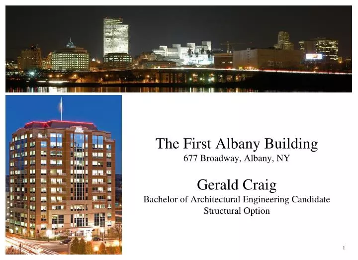
The First Albany Building 677 Broadway, Albany, NY Gerald Craig Bachelor of Architectural Engineering Candidate Structural Option. 1.

E N D
The First Albany Building677 Broadway, Albany, NYGerald CraigBachelor of Architectural Engineering CandidateStructural Option 1
The First Albany Building677 Broadway, Albany, NY- Downtown Albany- Near state and government offices- Conveniently located off of I-787- 12 Stories + Elevator Penthouse • Building Uses: • Angelo’s 677 Prime • General office space • Condominiums (possible future use) 2
The First Albany Building677 Broadway, Albany, NYStructural Systems: - Foundation - First floor at grade, no basement - Steel H-Piles - Grade Beams - Floor System - Composite Steel & Concrete Design (partial composite action) - Resists gravity forces & loads only - Simply Supported Beams - Lateral Force Resisting System - Structural Steel, Concentrically Braced Frames Partial Composite Action Braced Frames 3
The First Albany Building677 Broadway, Albany, NYStructural Systems Design Requirements:- Live Loads- Office Space (2-8) & Partitions, 75 psf - Office Space (9-12) with Access Flooring for computer use & Partitions, 115 psf - Office Space (2) with file storage, 125 psf - Little significant seismic activity- Seismic Design Category B - Small potential ground accelerations (SDS = 0.28, SD1 = 0.12) - No extreme wind conditions- Minimum design wind velocity (v = 90 mph) FIGURE 6-1C DESIGN WIND VELOCITY 4
A New Building - Visually identical Building - Identical Building Use - New proposed location - Charleston, South Carolina - commercial sector - last exit off from I-26 - height limitations (50-80 ft) - zoning variances are considered (report – appendix E) - go ahead with project for educational purposes 5
A New Building - Slightly Altered Building Core Layout - Elevators Relocated - Symmetric Core Layout - Little effect on foot-traffic Existing Building Layout Proposed Building Core Layout Exiting Building Core Layout Proposed Building Layout 6
A New BuildingCharleston, SC Structural Systems Design Requirements: - Live Loads (same as previous) - Office Space (2-8) & Partitions, 75 psf - Office Space (9-12) with Access Flooring for computer use & Partitions, 115 psf - Office Space (2) with file storage, 125 psf - Reduced as allowed per (ASCE 7-05 4.8) - Snow Loads - As calculated, 5 psf - More chance of significant seismic activity - Seismic Design Category D (SDS = 0.991, SD1 = 0.406) - Hurricane prone area - High design wind velocity (v = 140 mph) 7
A New BuildingCharleston, SC Structural Floor System Design: - Main Objective: Reduce Effective Seismic Weight - Thinner Floor Deck & Slab - 22 gage B-LOK 1.5”x 6” DECK, (United Steel Deck Catalog) - f’c = 4 ksi (lightweight concrete) - Total Slab Thickness = 4” - Weight = 1.6 psf (Composite Weight = 29 psf) - ФVnt = 2980 # (Vu = 930.9 #) - ФMno = 25.66 in-K (no studs present, conservative, Mu = 19.2 in-K) - Maximum Un-shored Span = 6.91’ (maximum beam spacing = 6.88’) - AWWF = 0.023 in² per ft - Full Composite Action (Beams) - Floor member strength controlled by the amount of concrete in compression rather than the shear stud connectors ability to transfer forces from the steel beam to the concrete slab. - Reduces structural steel weight by ~20% - Increases shear stud connector count by ~130% - Design method & calculations found in Appendix A 8
A New BuildingCharleston, SC Selecting a Lateral Force Resisting System : - Main Objective: Provide Stability & Stiffness - Special Reinforced Concrete Shear Walls - Response Modification Factor (R) = 6 (verses R = 5 for Composite Steel & Concrete Concentrically Braced Frames) - Educational value of earthquake resistant shear wall design - Adds considerable seismic weight - ASCE 7-05 Table 12.2-1 Height Limitation of 160’:12.2.5.4 Increased Building Height Limit for Steel Braced Frames and Special Reinforced Concrete Shear Walls. The height limits in Table 12.2-1 are permitted to be increased from 160 ft (50 m) to 240 ft (75 m) for structures assigned to Seismic Design Categories D or E and from 100 ft (30 m) to 160 ft (50 m) for structures assigned to Seismic Design Category F that have steel braced frames or special reinforced concrete cast-in-place shear walls and that meet both of the following requirements: 1. The structure shall not have an extreme torsional irregularity as defined in Table 12.2-1 (horizontal structural irregularity Type 1b). 2. The braced frames or shear walls in any one plane shall resist no more than 60 percent of the total seismic forces in each direction, neglecting accidental torsional effects. 9
A New BuildingCharleston, SC Dynamic Lateral Analysis (Seismic): - 3D Mathematical Model created using ETABS - “Cracked” sections were considered - Beams - 0.35Ig - Column - 0.70Ig - Shear Walls – 0.5f22 - Effective seismic weight (applied as a uniform additional mass) - Steel Beams & Columns ~5.1 psf - Other Dead Loads ~77.1 psf - Core Structure as calculated (in report, Appendix C) - Modal Superposition - Less conservative / more accurate - Equivalent Lateral Force Method not permitted by ASCE 7-05 Table 12.6-1Ts = SD1 / SDS = 0.406 / 0.991 = 0.4097 T < 3.5Ts ? (3.5*0.4097=1.434) Tc = 1.6199 (calculated north-south) Tc = 1.2702 (calculated east-west)- Modal Participating Mass ratios > 90% as per ASCE 7-05 12.9.1- Modal Combination, Complete Quadratic Combination- Base Shear lower limit (12.9.4) - 85% of base shear from ELF method - scale factor of 1.047 added to E-W direction - N-S direction base shear > 85% ELF method 10
A New BuildingCharleston, SC Dynamic Lateral Analysis (Seismic): - Structure Irregularities (12.3.2) - Torsional & Extreme Torsional Irregularity - Maximum ratio of extreme drift and average drift is about 1.1 (<1.2 for torsional irregularity) - No major Re-entrant Corner Irregularity - Ratios all less than 15% - No Diaphragm Discontinuities - No Out of Plane Offsets - System is parallel & symmetric - No Vertical Irregularities - No single story stiffness is less than the story above - Effective seismic weight is relatively constant - Lateral system is uniform- Redundancy Factor (12.3.4.2) - The value of ρ shall be taken as 1.3 - Removal of a shear wall results in extreme torsional irregularity - Torsional Amplificaiton Factor (12.8.4.3) - Unnecessary, Type 1a or 1b torsional irregularity does not exist- Direction of Loading (12.5.4) -Since the structure does not display any horizontal irregularities (specifically type 5), loads in each of the orthogonal directions are considered independently. Core Structure 11
A New BuildingCharleston, SC Lateral Analysis (Wind):- Design Wind Pressures - Design wind velocity, 140 mph - Open, Flat Terrain - Applied as per ASCE 7-05 Figure 6.9 Wind Pressure N-S Wind Pressure E-W 12
A New BuildingCharleston, SC Design Forces: - Load Combinations: ASCE 7-05 2.3- #1: 1.4D - #2: 1.2D + 1.6L + 0.5S - #3: 1.2D + 1.6S + 0.8W - #4: 1.2D + 1.6W + 1.0L + 0.5S - #5: 1.2D + 1.0E + 1.0L + 0.2S => (1.2 + 0.2SDS)D + ΩOQE + L + 0.2S - #6: 0.9D + 1.6W + 1.6H - #7: 0.9D + 1.0E + 1.6H => (0.9 − 0.2SDS)D + ΩOQE + 1.6H - Strength Requirements: - Wind loads controlled strength requirements for the lower floors - Seismic loads controlled strength requirements for the upper floors Element Forces 13
A New BuildingCharleston, SC Lateral Structural System Design:Lightweight concrete was taken advantage of for floors 5 through the roof. All appropriate properties of lightweight concrete were considered (λ = 0.75, Ec = 33w1.5√f’c = 2900 ksi). Normal weight concrete was used in the lower floors due to higher required strengths and limitations in ACI 3-18 21.1.4.3 Specified compressive strength of lightweight concrete, f’c, shall not exceed 5000 psi unless demonstrated by experimental evidence that structural members made with that lightweight concrete provide strength and toughness equal to or exceeding those of comparable members made with normal weight concrete of the same strength. 14
A New BuildingCharleston, SC Lateral Structural System Design (Continued) : - Typical Column Design: To satisfy ACI 3-18 Sections 21.6.4 & 21.6.5, transverse reinforcement (hoops) must be spaced at maximum of 3” for a distance greater than or equal to 1/6th of the clearspan (lo)from each joint face, and at 6” (maximum) along the rest of the length. The first hoop shall be placed less than 2” from joint face. Transverse Reinforcement (within lo):Ash ≥ 0.3[(s)(bc)(f’c)/(fyt)]/[(Ag/Ach)-1] = 0.49 in² (for s = 3” and f’c = 5 ksi) Ash ≥ 0.09[(s)(bc)(f’c)/(fyt)] = 0.38 in² (for s = 3” and f’c = 5 ksi) Ash ≥ 0.3[(s)(bc)(f’c)/(fyt)]/[(Ag/Ach)-1] = 0.81 in² (for s = 3” and f’c = 8 ksi)Ash ≥ 0.09[(s)(bc)(f’c)/(fyt)] = 0.61 in² (for s = 3” and f’c = 8 ksi) From these requirements, #4 hoops & ties are selected (Ash = 0.60 in²) for where f’c = 5 ksi and #5 hoops & ties are selected (Ash = 0.93 in²) for where f’c = 8 ksi. - Column Shear Strength: (Vu max = 93.5 K) (Vu max = 76 K) 15
A New BuildingCharleston, SC Lateral Structural System Design (Continued) : - Column Axial & Flexural Strength: “PCA Column” was used to check flexural and axial combinations. Full documentation and interaction diagrams can be found in Appendix G. (Moment Capacities are for biaxial flexure @ each axial load) • Column Design Summary: - Longitudinal (Flexural & Axial) Reinforcement (8) #9s distributed evenly around 4 faces - Transverse Reinforcement – Supporting Floors 5 - PH #4 hoops & ties @ 3” O.C. within lo(1/6th of the clearspan from each joint face) #4 hoops & ties @ 6” O.C. in middle sections Supporting Floors 2 - 4 #5 hoops & ties @ 3” O.C. within lo(1/6th of the clearspan from each joint face) #5 hoops & ties @ 6” O.C. in middle sections 16
A New BuildingCharleston, SC Lateral Structural System Design (Continued): - Typical Beam Design: As per ACI 3-18 Sections 21.5.3, transverse reinforcement (hoops) must be spaced at maximum of 3.5” (d/4 = 3.86”) for a distance greater than or equal to twice the member depth (lo) from face of each support, and at 7” (d/2 = 7.72”) along the rest of the length. The first hoop shall be placed less than 2” from face of support. - Beam Shear Strength: 17
A New BuildingCharleston, SC Lateral Structural System Design (Continued): - Beam Flexural Strength: • Beam Design Summary: Longitudinal (Flexural) Reinforcement All Supported Floors (5) #9s distributed evenly @ each face (2) #9s placed in middle on each side Transverse Reinforcement – All Supported Floors #3 hoops & ties @ 3.5” O.C. within lo(2x member depth from face of support) #3 hoops & ties @ 7” O.C. in middle sections 18
A New BuildingCharleston, SC Lateral Structural System Design (Continued): - Shear Wall Design: 19
A New BuildingCharleston, SC Lateral Structural System Design (Continued): - Boundary Elements: Special boundary elements not needed Flexural & Axial Strength: Shear Walls - Considering (20)#9s as flexural reinforcement for each of the walls, the following results are calculated. Walls 3,4,5 Supporting Floors 2-4 (f’c = 8 ksi): Walls 3,4,5 Supporting Floors 5-PH (f’c = 5 ksi) Walls D,E Supporting Floors 2-4 (f’c = 8 ksi): Walls D,E Supporting Floors 5-PH (f’c = 5 ksi) • Wall Design Summary: Flexural Reinforcement – All Supported Floors (20) #9s distributed evenly, 10 @ each edge Longitudinal Reinforcement – All Supported Floors (2)#5s at 16” O.C. Max (1 each face)Transverse (Shear) Reinforcement – All Supported Floors (2)#5s at 16” O.C. Max (1 each face). 20
A New BuildingCharleston, SC Lateral Structural System Design (Continued): - Typical Details: 21
A New BuildingCharleston, SC Drifts: For the overall design, drifts due to wind loads are the controlling factor. The level of structural stiffness needed to limit drifts (due to wind) to 0.25% or L/400 provides enough lateral strength to carry all seismic and wind load combinations. L/400 is used as a drift limit due the presence of exterior brick veneer that is sensitive to excessive displacements. Drifts due to seismic loads, which are limited to 0.020hx (2%), can be found in Appendix H. Foundation ConsiderationsOverturning:The increased design wind velocity results in an increased overturning moment. The current foundation would have to be altered, namely the number of piles supporting the shear walls. The overturning moments of the existing building are roughly 80,000 ft-k (between 2 wide frames) in one direction and 60,000 ft-k in the other (between 3 narrow frames). Overturning moments in the new structure are roughly 135,000 ft-k and 113,000 ft-k. Other Considerations:Other foundation changes would be needed to fully support the shear walls along their lengths. A foundation design for the new structure was beyond the scope of this project. 22
A New BuildingCharleston, SC Construction Schedule & Cost Impact:The First Albany Building took 24 months to build and cost roughly $25 million (excluding design service and property costs). The original schedule was a rotating 5 week schedule per floor (generally speaking) and total construction time was projected at 26 months. Taking into consideration the changes made through out this thesis project, the overall schedule was minimally affected. The same rotating 5 week schedule is projected to be sufficient. The original schedule was controlled by the time needed by the mechanical, electrical, and plumbing trades; roughly 5 weeks per floor level. Construction of the concrete shear walls could be completed nearly in parallel with the structural steel erection. Shifting the shear wall construction phase (per floor) to slightly lead the steel erection phase would provide the time necessary to remove concrete formwork and allow the structural steel to be connected to the shear wall. The building layout and size would allow for a single crane to operate from one location for the entire project, with the location depending on the exact site layout (property setbacks, surrounding space). A projected construction schedule can be found in Appendix I. Considerations specifically taken into account for creating the schedule include coordinating the three principle trades (MEP) in such a fashion that they aren’t interfering in each other’s work and which tasks/phases can be overlapped. The projected schedule spans 26 months from breaking ground to installing the last outlet cover. 23
A New BuildingCharleston, SC Construction Schedule & Cost Impact (Continued):Considering a building that is identical to the First Albany Building except for the new structural system designed for a location in Charleston, the cost of the building is projected to increase. This is mainly due to the need for a more robust lateral structural system. Switching to full composite action and choosing a thinner floor slab (decrease from 4.5” to 4”) does reduce material costs, but is offset by extra labor required for shear stud connector installation. Labor costs remain unchanged for the slab since costs are based square footage rather than volume of concrete placed. Overall Steel fabrication and erection costs for the floor system also remain relatively unchanged because the only factor that changed was raw tonnage of steel (same number of pieces, but smaller shapes). 24
A New BuildingCharleston, SC Conclusions:This project was an excellent exercise in structural design.Original Expectation: - Design controlled by seismic forces Incorporated Topics: - Proper usage of computer modeling software (ETABS) - Dynamic analysis - Reinforced concrete design - Composite steel & concrete design - Earthquake resistant designOutcomes: - Design controlled by drift limitations (Wind) - Strength controlled by wind forces in lower floors, seismic forces in upper floors. - Thicknesses of 16” & 20” in each or the orthogonal directions - Design could be used along much of the east coast - Concrete reinforcement detailing mostly prescriptive(can see reasoning for reinforcement requirements in many pictures from the recent earthquake in Haiti) 25
A very large Thank you to the people at Columbia Development CompaniesThank you to the Architectural Engineering facultyAnd finally, a HUGE thank you goes to my wife, Courtney. Without her support and perseverance, none of this would have been possible.Questions 26