Download
1 / 34
380 likes | 622 Views
Block Diagram of Intel 8086. Engr.M.Zakir Shaikh Visiting Faculty I.B.T LUMHS Research Associate Mehran UET. Intel 8086. Intel 8086 was launched in 1978. It was the first 16-bit microprocessor. This microprocessor had major improvement over the execution speed of 8085.

E N D
Block Diagram of Intel 8086 Engr.M.Zakir Shaikh Visiting Faculty I.B.T LUMHS Research Associate Mehran UET
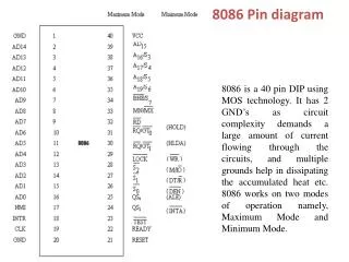
Intel 8086 • Intel 8086 was launched in 1978. • It was the first 16-bit microprocessor. • This microprocessor had major improvement over the execution speed of 8085. • It is available as 40-pin Dual-Inline-Package (DIP).
Intel 8086 • It is available in three versions: • 8086 (5 MHz) • 8086-2 (8 MHz) • 8086-1 (10 MHz) • It consists of 29,000 transistors.
Intel 8086 • It has a 16 line data bus. • And 20 line address bus. • It could address up to 1 MB of memory. • It has more than 20,000 instructions. • It supports multiplication and division.
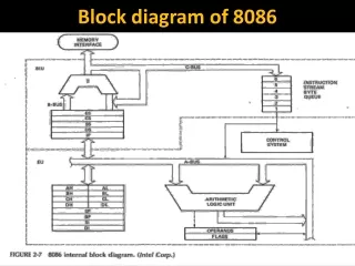
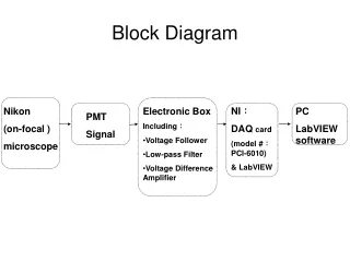
Block Diagram of Intel 8086 General Purpose Registers, Pointers & Index Registers Segment Registers & Instruction Pointer Address Lines Data Lines BHE/S7, RD, WR, INTA, ALE, DT/R, DEN CLK Control Lines VCC GND MN / MX
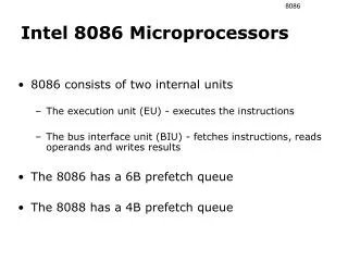
Block Diagram of Intel 8086 • Intel 8086 contains two independent functional units: • Bus Interface Unit (BIU) • Execution Unit (EU)
Bus Interface Unit • Bus Interface Unit contains: • Segment Registers • Instruction Pointer • 6-Byte Instruction Queue
Execution Unit • Execution Unit contains: • General Purposes Registers • Stack Pointer • Base Pointer • Index Registers • ALU • Flag Register • Instruction Decoder • Timing & Control Unit
Functions of Bus Interface Unit It handles transfer of data and addresses between the processor and memory / IO. It reads data from memory and I/O devices. It writes data to memory and I/O devices. It computes and sends out addresses. It fetches instruction codes. It stores fetched instruction codes in a FIFO register called QUEUE.
Instruction Queue To increase the execution speed, BIU fetches as many as six instruction bytes ahead to time from memory. All six bytes are then held in first-in-first-out 6-byte register called instruction queue. Then all bytes are given to EU one by one. This pre-fetching operation of BIU may be in parallel with execution operation of EU, which improves the execution speed of the instruction.
Functions of Execution Unit • It receives opcode of an instruction from the QUEUE. • It decodes it and then executes it. • It tells BIU where to fetch the instructions or data from. • It contains the control circuitry to perform various internal operations. • It has 16-bit ALU, which can perform arithmetic and logical operations on 8-bit as well as 16-bit data.
Pipelining While EU executes instructions, BIU fetches instructions from memory and stores them in the QUEUE. BIU and EU operate in parallel independent of each other. This type of overlapped operation of the functional units of a MP is called Pipelining.
Registers of Intel 8086 • Intel 8086 contains following registers: • General Purpose Registers • Pointer and Index Registers • Segment Registers • Instruction Pointer • Status Flags
General Purpose Registers • There are four 16-bit general purpose registers: • AX • BX • CX • DX
General Purpose Registers Each of these 16-bit registers are further subdivided into two 8-bit registers. AX BX CX DX
General Purpose Registers • AX Register: AX register is also known as accumulator register that stores operands for arithmetic operation like divided, rotate. • BX Register: This register is mainly used as a base register. It holds the starting base location of a memory region within a data segment. • CX Register: It is defined as a counter. It is primarily used in loop instruction to store loop counter. • DX Register: DX register is used to contain I/O port address for I/O instruction.
Pointer and Index Registers • Following four registers are under this category: • Stack Pointer (SP) • Base Pointer (BP) • Source Index (SI) • Destination Index (DI)
Pointer and Index Registers • Stack Pointer (SP): • The function of SP is same as the function of SP in Intel 8085. • It stores the address of top element in the stack. • BP, SI & DI are used in memory address computation. (Will be discussed later)
Segment Registers • There are four segment registers in Intel 8086: • Code Segment Register (CS) • Data Segment Register (DS) • Stack Segment Register (SS) • Extra Segment Register (ES)
Segment Registers • In 8086, memory is divided into four segments: • Code Segment • Data Segment • Stack Segment • Extra Segment
Segment Registers • A segment register points to the starting address of a memory segment. • For e.g.: • The code segment register points to the starting address of the code segment. • The data segment register points to the starting address of the data segment, and so on. • The maximum capacity of a segment may be up to 64 KB.
Segment Registers • The instructions of 8086 specify 16-bit address. • But the actual physical addresses are of 20-bit. • Therefore, they are calculated using the contents of the segment registers and the effective memory address. • (Will be discussed later)
Instruction Pointer • The Instruction Pointer (IP) in 8086 acts as a Program Counter. • It points to the address of the next instruction to be executed. • Its content is automatically incremented when the execution of a program proceeds further. • The contents of the IP and Code Segment Register are used to compute the memory address of the instruction code to be fetched. • This is done during the Fetch Cycle.
Status Flags Status Flags determines the current state of the accumulator. They are modified automatically by CPU after mathematical operations. This allows to determine the type of the result.
Status Flags Flag Register of 8086 8086 has 16-bit status register. It is also called Flag Register or Program Status Word (PSW). There are nine status flags and seven bit positions remain unused.
Status Flags • 8086 has 9 flags and they are divided into two categories: • Condition Flags • Control Flags
Status Flags Following are the nine flags:
Condition Flags Condition flags represent result of last arithmetic or logical instruction executed. Conditional flags are as follows: Carry Flag (CF): This flag is set if there is a carry / borrow after an integer arithmetic. Auxiliary Carry Flag (AF): If an operation performed in ALU generates a carry / borrow from lower nibble (i.e. D0 – D3) to upper nibble (i.e. D4 – D7), then AF is set. It is used in BCD Addition. Parity Flag (PF): This flag is used to indicate the parity of result. If the result contains even number of 1’s, the Parity Flag is set and for odd number of 1’s, the Parity Flag is reset.
Condition Flags • Zero Flag (ZF): It is set; if the result of arithmetic or logical operation is zero else it is reset. • Sign Flag (SF): In sign magnitude format the sign of number is indicated by MSB bit. If the result of operation is negative, sign flag is set. • Overflow Flag (OF): It occurs when signed numbers are added or subtracted. An OF indicates that the result has exceeded the capacity of machine.
Control Flags • Control flags are set or reset deliberately to control the operations of the execution unit. Control flags are as follows: • Trap Flag (TP): • It is used for single step control. • It allows user to execute one instruction of a program at a time for debugging. • When trap flag is set, program can be run in single step mode.
Control Flags • Interrupt Flag (IF): • It is an interrupt enable / disable flag. • If it is set, the INTR interrupt of 8086 is enabled and if it is reset then INTR is disabled. • It can be set by executing instruction STI and can be cleared by executing CLI instruction.
Control Flags • Directional Flag (DF): • It is used in string operation. • If it is set, string bytes are accessed from higher memory address to lower memory address. • When it is reset, the string bytes are accessed from lower memory address to higher memory address. • It is set with STD instruction and cleared with CLD instruction.
Thank You Have a Nice Day