Download
1 / 41
410 likes | 487 Views
NRM L06. Systems, domains and causal networks. Andrea Castelletti. Politecnico di Milano. 2. Conceptualisation. Defining Criteria and Indicators. Defining Actions (measures). Identifying the M odel. 1. Reconnaissance. Stakeholders. Schema fisico. Physical scheme of the system.

E N D
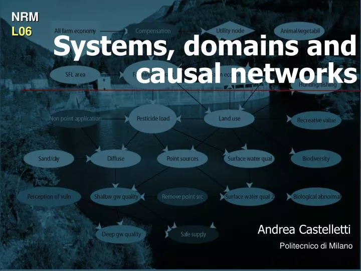
NRM L06 Systems, domains and causal networks Andrea Castelletti Politecnico di Milano
2. Conceptualisation Defining Criteria and Indicators Defining Actions (measures) Identifying the Model 1. Reconnaissance Stakeholders
Schema fisico Physical scheme of the system Interceptors 1350 m. CAMPOTOSTO Vomano PROVVIDENZA (P) Chiarino Fucino PROVVIDENZA Gronda 1100 m. PIAGANINI SAN GIACOMO (SG) Left interceptor 400 m. Right interceptor 400 m. Water works MONTORIO (M) VILLA VOMANO Irrigation district (CBN) S. LUCIA (SL) Adriatic Sea Component: modelling elementary unit. Every component has a specific function. The model of the component must describe such a fuction. Logical components are also allowed. • Choosing the components depends on: • relevance of the component to the objective of the modelling exercise • data availability
Identifying the Model • Definining the components and the system scheme • Identifying the models of the components • Aggregated model
Schema fisico Irrigation District (CBN) Interceptors 1350 m. CAMPOTOSTO Vomano PROVVIDENZA (P) Chiarino Fucino PROVVIDENZA Interceptor 1100 m. PIAGANINI SAN GIACOMO (SG) Left interceptor 400 m. Right interceptor 400 m. MONTORIO (M) Water works VILLA VOMANO S. LUCIA (SL) Adriatic Sea
Irrigation district (CBN) Data analysis: time series provided by Enel Campotosto: • level • aggregated daily flow rate the two intereceptors Piaganini and Provvidenza: • level • daily flow rate from mass balance Interceptors 1350 m. CAMPOTOSTO Vomano PROVVIDENZA (P) Fucino Chiarino PROVVIDENZA e.g. Provvidenza: Interceptor 1100 m. PIAGANINI SAN GIACOMO (SG) Left interceptors 400 m. only aggregated flow data Water works Right interceptor 400 m. MONTORIO (M) During night-time without pumping VILLA VOMANO S. LUCIA (SL)
Schema fisico Irrigation District (CBN) Interceptors 1350 m. CAMPOTOSTO Vomano PROVVIDENZA (P) Chiarino Fucino PROVVIDENZA Interceptor 1100 m. PIAGANINI SAN GIACOMO (SG) Left interceptor 400 m. Right interceptor 400 m. MONTORIO (M) Water works VILLA VOMANO S. LUCIA (SL) Adriatic Sea
Schema fisico (bacini) Irrigation district (CBN) CAMPOTOSTO PROVVIDENZA (P) Fucino PROVVIDENZA PIAGANINI Water works ??? SAN GIACOMO (SG) MONTORIO (M) VILLA VOMANO S. LUCIA (SL) Adriatic Sea
Average water supply from hydropower reservoirs WW Some difficulties in the scheme 1. Piaganini:there is no way to compute the indicator for the water works ?
How to solve them… We need to fix a criterion for disaggregating the total inflow in the two single contributions of the interceptors. How? Based on the surface and the morphological characteristics of the two catchments (regional analysis) we can assume a similar contribution from the two interceptors. The hypothesis is validated using some flow rate measures locally available on the interceptors.
Some difficulties in the scheme 1. Piaganini: there is no way to compute the indicator for the water works 2. Campotosto: the contribution from the natural catchment is not accounted for.
100 km2 Affluenti Campotosto Campotosto
Some difficulties in the scheme 1. Piaganini: there is no way to compute the indicator for the water works 2. Campotosto: the contribution from the natural catchment is not accounted for. 3. Provvidenza e Piaganini: understimation of snow-melting in spring and evaporation in summer.
Possible solutions 1. Piaganini: there is no way to compute the indicator for the water works 2. Campotosto: the contribution from the natural catchment is not accounted for. 3. Provvidenza e Piaganini: understimation of snow-melting in spring and evaporation in summer. The daily inflow can be computed via mass balance using release and pumping data: Campotosto Provvidenza Piaganini
Snow melt is negligible evaporation is NOT negligible Piaganini The estimate is reliable: we can use the new data obtained via mass balance (red) instead of those provided by Enel (blue).
Provvidenza The estimate is not reliable. Pumping is adding noise to data. An understimation of evaporation is anyway evident in the data by Enel. These data can be corrected by removing from them the evaporation that can be obtained from Piaganini, based on the many similarities between the two reservoirs.
Some difficulties in the scheme 1. Piaganini: there is no way to compute the indicator for the water works 2. Campotosto: the contribution from the natural cacthment is not accounted for. 3. Provvidenza e Piaganini: understimation of snow-melting in spring and evaporation in summer.
this is impossible: at 40° max evap. 3m3/s Campotosto Estimate is not reliable. Oscillation are wider than in Provvidenza: Pumping, but also the instrument precision (1cm) is amplifying the error The contribution from the natural catchment is evident, but not easily quantifiable. Inflow from Enel (blue) and from water balance (red) are not usable. What can we do?
Interceptors 1350 m Provvidenza Piaganini CAMPOTOSTO Reservoir The valure for each year is obtained Montorio Natural inflow to Campotosto Can we evaluate the significancy of the inflow contribution from the natural Campotosto’s catchment? Water balance for the i-th year in Montorio - Internal pumping to the system - Error on the level negligible The estimate is an annual value: how to move to a daily one? From which
Inflow estimate in Campotosto evaporation
Some difficulties in the scheme 1. Piaganini: there is no way to compute the indicator for the water works 2. Campotosto: the contribution from the natural cacthment is not accounted for. 3. Provvidenza e Piaganini: understimation of snow-melting in spring and evaporation in summer.
Schema fisico Irrigation District (CBN) CAMPOTOSTO PROVVIDENZA (P) Fucino PROVVIDENZA PIAGANINI Topological Scheme SAN GIACOMO (SG) MONTORIO (M) VILLA VOMANO S. LUCIA (SL) Adriatic Sea
Identifying the Model • Definining the components and the system scheme • Identifying the models of the components • Aggregated model
Schema fisico Irrigation District (CBN) CAMPOTOSTO PROVVIDENZA (P) Fucino PROVVIDENZA PIAGANINI SAN GIACOMO (SG) MONTORIO (M) VILLA VOMANO S. LUCIA (SL) Adriatic Sea
Campotosto lake Simplification Let’s assume that only one criterion needs to be satisfied: flood reduction in the town of Campotosto (on the lake shores)
The (lake’s) domain The whole set of quantities and information about the lake: • inflow • release • level • water characteristics • biota • algae • ... • batimetry • topography • stage-discharge function of the spillway • ... • Consorzio dell‘Adda (lake manager) • Regione Lombardia (water authority) • ... (at+1) Models are a simplified representation of reality; They should reproduce those features of the system that are important for the scope of the Project. The first step to create a model is to select the essential variables within the domain. (rt+1) (ht) The domain is the first level of abstraction of reality. It does not require any assumption about the mathematical relationships linking the variables. It is not a representaton of reality, but a partition of knowledge.
The (lake’s) domain The whole set of quantities and information about the lake: • inflow • release • level • water characteristics • biota • algae • ... • batimetry • topography • stage-discharge function of the spillway • ... • Consorzio dell‘Adda (lake manager) • Regione Lombardia (water authority) • ... (at+1) (rt+1) (ht) An important convention The subscript of a variable is the time instant at which it takes deterministically known value.
et+1 at+1 Are the variables well defined? It is very important that the domain is defined in strict collaboration with the concerned Stakeholders. Sharing and agreeing on the assumptions made at this point is key to obtain a “trusted” model of the system. Inflow at+1: total inflow in the interval [t,t+1) It is better to divide it into: et+1 = inflow from the natural catchment wt = pumping from hydropower plant downstream wt Which unit of measurement? m3/s or m3 ? Are the variables well defined? YES, as long as we do not find errors: only falsification is possible.
Identifying the model:the causal network Release decision Is it a good representation of the real cause-effect relationships?
Causal network of the lake Loops are not allowed. An effect can not cause itself!! Is it a good model of reality? NO, evaporation is missing....
Causal network of the lake How to check if the network is a good model? - A priori: good sense, Analyst’s intuition - A posteriori: accuracy of the model identified starting from the network
deterministic disturbance disturbance input input internal variables disturbance input random disturbance Classification of the variables state control output The stateis composed of all the variables that are necessary to describe the past history of the system, and, once these are known, the future evolution of the system is completely defined by the sole inputs.
set of the feasible controls output transformation function The model structure state transition function These two equations include all the information available in the network. In the network the internal variables are explicitely considered.
up planning decision wtdeterministic disturbance utcontrol et +1 random disturbance input From now on vectors will be in bold, e.g.xt is the state vector ! In general: variables state xt ouptut yt
Models interact with the outside only through inputs and ouputs. What happens inside is important only as far as it affects the ouptuts. time-varying model In general: structure state transition function This is a DYNAMIC SYSTEM Models are OBJECTS in the computer-science meaning of the word with the following associated expressions output transformation function proper model improper model
et+1incoming flow model utwithdrawal decision yt diverted flow only the output transformation function yt=ht(ut,et+1) ! Time-varying is not a synonymus of dynamic Not always systems are dynamic Not always the state appears in the system dynamics. E.g.: diversion dam this is a non-dynamic model
given the initial state Simulation established a time horizon H (starting from time 0 and ending at time h) the input trajectories simulation is aimed at computing the state trajectories the output trajectories
given the initial state Simulation established a time horizon H (starting from time 0 and ending at time h) the input trajectories using the model recursively 38
causal network mental model Conclusions domain • Next step: • implicitly or explicitly define • the state transition function • - the output transformation function How to classify model ? with respect to the aumount of a priori information one has to know about the ongoing processes the nature of their functions
Bayesian Believe Networks • Mechanistic models • Empirical models • Markov models
Readings IPWRM.Theory Ch. 4