Download
1 / 23
230 likes | 242 Views
Enabling Carrier Aggregation <br>Enabling Carrier Aggregation

E N D
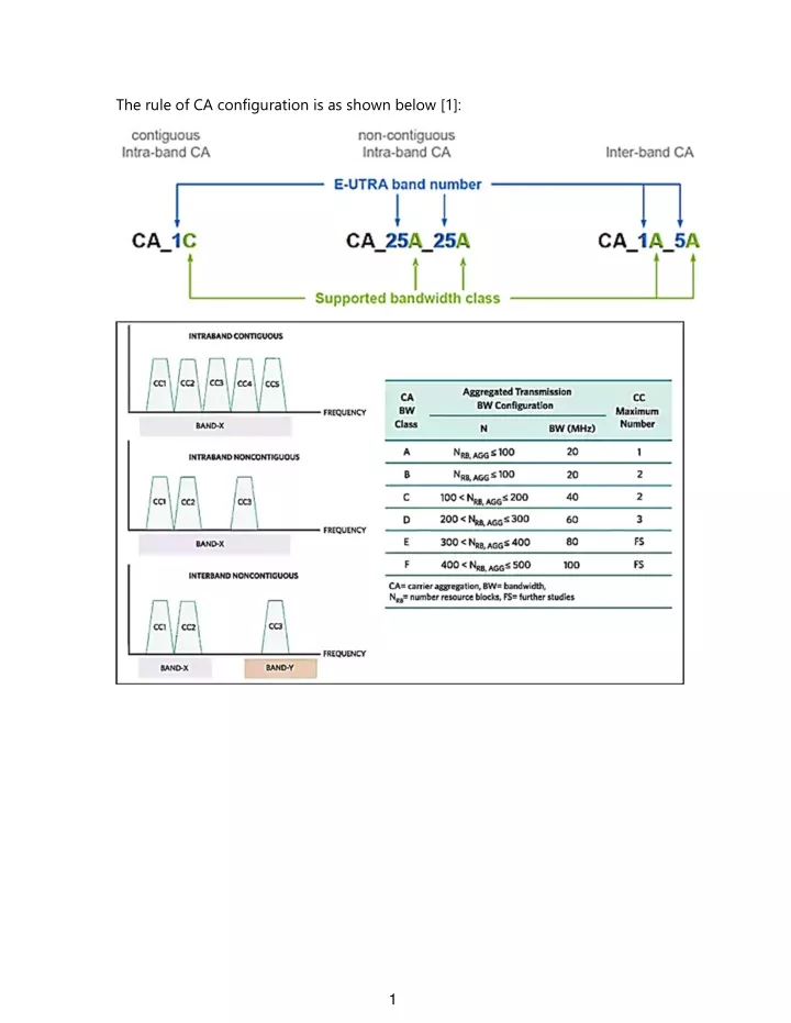
CA can be used by both LTE frame structures; meaning by both FDD and TDD, and it can be enabled for both DL and UL direction [1]. That is, there would be (FDD-FDD), (TDD-TDD), and (FDD-TDD) combinations. As for inter-band: CA_C_B2 CA_NC_B2 The middle “C” means contiguous; “NC” means non-contiguous. One thing is worth mentioning. If the combination is (TDD-TDD), such as (B39-B41), timing is crucial. Regarding inter-band, TDD-TDD CA scenario, if there’s an overlap between TX and RX timing, there would be in-band and cross-band interference [3]. 2
The CA combination is very flexible. You can combine different scenarios, bands, and bandwidth. Allocating more CCs to a UE generally results in a higher throughput thanks to the larger bandwidth. Nevertheless, as for UL CA, it is NOT sure entirely. According to the formula, more CCs leads to higher PAPR, which needs higher linearity. That’s why UL adopts SC-FDMA in LTE. If the linearity is not good enough, the EVM will increase, and the SNR would degrade since EVM is inversely proportional to SNR. According to the Shannon theorem, poor SNR aggravates the data rate. Thus, whether UL CA enhances data rate or not depends on TX chain linearity. For UL CA, more CC number does NOT lead to higher throughput necessarily. That’s why DL is always larger than UL in CC numbers [1]. 3
Compared to DL CA, UL CA design is more challenging, especially in linearity. The spectrum of TX signals is as shown below [4]: As for the intra-band contiguous scenario, we can regard it as a signal with broader bandwidth, which brings high PAPR.And, high linearity of PA is required even though MPR (Maximum Power Reduction) is implemented. Besides, self- heating and wide bandwidth are key sources to the memory effect in PAs, which results in asymmetric ACLR. 4
As for intra-band non-contiguous scenario, Take RX signal 1, for example, which would be corrupted by both TX signal 1 (relevant to duplex spacing) and TX signal 2 (related to band-gap). In particular, the situation often occurs in (low channel CC – high channel CC) combination. If the band-gap is very narrow, such as B8 (band-gap = 10 MHz), the issue may worsen further. This situation means that the ACLR of each CC must be low enough not to aggravate sensitivity, which puts more strict demands on PAs [4]. 5
Unlike Intra-Band UL CA, because CCs are in different bands, there may not be high PAPRs and RX band noise issues. Since the transmit power is reduced for each due to MPR, the PA linearity isn’t an issue. Nevertheless, other front‐end components, like switches, have to deal with high‐level signals from different bands that can mix and create intermodulation products, which can interfere with one of the active cellular receivers. Thus, to manage these signals, switches must have very high linearity [2,4]. 6
Indeed, the aforementioned harmonic product issue occurs in inter-band UL CA as well. Additionally, since B4 TX is active during UL CA operation, the in-band isolation between B4 TX and B4 RX is also a concern. Consequently, as for inter-band UL CA, we have to deal with intermodulation issue for (LB-LB) or (MB-MB) combination, and harmonic product issue for (LB- MB) combination. The usual harmonic product interferences are as below: 3 * B17 => B4 2 * B8 => B3 3 * B8 => B7 7
As for Intra-band non-contiguous case, as long as the duplex spacing and band- gap as well as ACLR are low enough, the RX band noise would be mitigated. As for Inter-band case, as mentioned earlier, each UL CC has 3 dB less than a non‐CA signal. The intermodulation product can be mitigated by high linearity of ASMs and high antenna-to-antenna isolation. As for harmonic product issues, which can be reduced by high trace-to-trace isolation, high port-to-port isolation, and high antenna-to-antenna isolation [4]. Scenario Issue Mitigation Plan Large duplex spacing and band gap Low ACLR High linearity of ASM High Trace-to-Trace isolation of layout High port-to-port isolation of ASM High antenna-to-antenna isolation Intra-band non contiguous RX band noise Intermodulation product Inter-band Harmonic product Nevertheless, high PAPR due to intra-band contiguous case is inevitable, which means this issue can NOT be mitigated whatever method you adopt. Consequently, the scenario, Intra-band contiguous, is the most challenging. 8
This serving cell is referred to as the primary cell (PCell). In the DL, the carrier corresponding to the PCell is the Downlink Primary Component Carrier (DL PCC), while in the UL it is the Uplink Primary Component Carrier (UL PCC). Other serving cells are referred to as secondary cells (SCells) and are used for bandwidth expansion for the particular UE. The Rel-12 TDD-FDD CA design supports either a TDD or FDD cell as the primary cell [1]. 9
ASM PA PA For non-CA case, directly connecting two duplexers by one single antenna is allowed because multiple bands will NOT operate simultaneously. However, for the CA case, the two bands operate simultaneously. Directly connecting two duplexers by one single antenna can affect each other’s filter characteristic, thereby losing the isolation. That is, this approach causes both in- band and cross-band interference issues through duplexer and ASM. 10
Consequently, for the CA case, we have to enhance the isolation between the two paths of the two bands. In general, four approaches can achieve this target: phase shifter, diplexer, distinct ASMs, and quadplexer. LB PA MHB PA As shown above, the diplexer enhances the isolation between the two paths and makes them able to operate simultaneously as well. Nevertheless, a diplexer is composed of LPF and HPF. That is, if the two bands are (LB-LB) or (MHB-MHB), this approach is not workable since a diplexer cannot separate two close bands. 11
As shown above, the phase shifter can enhance the isolation between two close bands, such as Band 1 and Band 3. 12
As shown above, the quadplexer can also enhance the isolation between two close bands, such as Band 1 and Band 3. For a multiplexer, both in-band and cross-band isolation need to be supported and at least 50 dB. Also, compared to the duplexer, the quadplexer has higher insertion loss. 13
Nevertheless, using the multiplexer reduces the throw count of the band select switch, which can be a significant benefit due to lower switch insertion loss and complexity, and this is especially beneficial to those non-CA bands. Therefore, in terms of loss, we have to compare the two scenarios: 1. Quadplexer + ASM with fewer ports 2. Duplexer + diplexer + ASM with more ports And, choose the lower one. 14
Using two distinct ASMs for LB and MHB individually is a workable approach as well. Since the two transmitting signals are NOT implemented in the same switch, there would be no intermodulation product. Nevertheless, as mentioned earlier, the isolation between the two antennas should be large enough to mitigate the harmonic product interference from LB. LB ASM LB PA MHB ASM MHB PA If there is no sufficient space to accommodate two antennas, you’re able to use a single antenna through a diplexer. LB ASM LB PA MHB ASM MHB PA 15
LB ASM LB PA -85 dBm MHB ASM MHB PA the LB harmonic levels must be attenuated to a level below –85 dBm before the diplexer. If this target can not be achieved, add an additional LPF [2]. LB PA A LB PA B In terms of harmonic product suppression, both A and B scenarios are identical. Nevertheless, in the B scenario, the loss of LPF is not added to RX path, but in A scenario, the loss of LPF is added to both TX and RX paths. Thus, the B scenario is better [3]. 16
SIMO is also known as receiving diversity, which is often used to enable a receiver system that receives signals from many independent sources to combat the effects of fading and enhance the sensitivity. For example, if the sensitivity is -97 dBm with a single antenna, the sensitivity would be -100 dBm approximately with two antennas. That is, due to another doubling of SNR (approximately 3dB), the data rate improves [3]. 17
In TDD, due to asymmetric and same bandwidth is shared by Uplink and Downlink in turn, so the total throughput is also shared accordingly.Take 20 MHz bandwidth for example, in FDD, a total of 40 MHz bandwidth is usable at any time. In TDD, merely 20 MHz bandwidth is usable at any time [4]. Consequently, increasing uplink performance is particularly vital for TDD-LTE because each band’s uplink data rates are limited by the fact that the same frequencies are used for uplink and downlink, with most capacity allocated to downlink [4]. After all, in terms of data rate, spectrum or bandwidth is always crucial. Again, as mentioned previously, TX-RX timing is very vital for (TDD-TDD) CA case. If TX and RX operate simultaneously, there would be severe in-band and cross-band interference. 18
It’s well known that Envelope Tracking (ET) is a power supply technique for improving the efficiency of PAs by tracking the envelope as opposed to today’s fixed power systems. Because intra-band CA involves the transmission of wideband signals with high peak-to-average ratios [2], which results in more power consumption. Thus, ET is more crucial than non-CA case. 19
For ET, it is crucial that Vcc and the RF input signal are aligned in time of the PA. Otherwise, these will be time delay between RF input signal and Vcc, thereby aggravating transmitter performance, such as ACLR and EVM [5]. Thus, proper time delay adjustment is necessary. 20
As shown above, this IC is ET DC-DC converter, which provides power supply to PA (i.e., Pin29, VSW), and C5513 (as marked blue circle) should be 470 pF. 21
Nevertheless, thanks to incorrect value (470 pF -> 47 nF), and the signal waveform is as shown below: In the intra-band contiguous UL CA case, the time delay between Vcc (yellow trace) and RF input signal is evident with a 47 nF shunt capacitor, thereby causing ACLR issue. High PAR means that the envelope varies more quickly and dramatically than low PAR, so the time delay of intra-band contiguous UL CA case is more severe than other cases. Indeed, with an external power supply (i.e., conventional fixed power supply) rather than ET DC-DC converter, the issue is gone. Consequently, the speed of Vcc variation is more crucial in intra-band contiguous ULCA scenario than other cases. 22
Reference [1] LTE Carrier Aggregation Technology Development and Deployment Worldwide [2] Enabling Carrier Aggregation [3] Carrier Aggregation Discussion [4] ABCs of Carrier Aggregation [5] Performance Requirement and lessons learnt of LTE Terminal_Transmitter Part 23