Download
1 / 17
460 likes | 1.79k Views
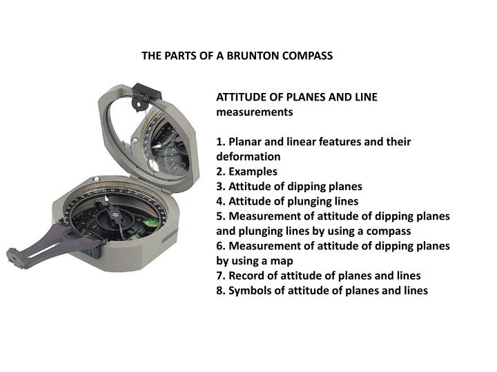
THE PARTS OF A BRUNTON COMPASS. ATTITUDE OF PLANES AND LINE measurements 1. Planar and linear features and their deformation 2. Examples 3. Attitude of dipping planes 4. Attitude of plunging lines 5. Measurement of attitude of dipping planes and plunging lines by using a compass

E N D
THE PARTS OF A BRUNTON COMPASS ATTITUDE OF PLANES AND LINE measurements 1. Planar and linear features and their deformation 2. Examples 3. Attitude of dipping planes 4. Attitude of plunging lines 5. Measurement of attitude of dipping planes and plunging lines by using a compass 6. Measurement of attitude of dipping planes by using a map 7. Record of attitude of planes and lines 8. Symbols of attitude of planes and lines
Components 2.1: magnetic needle • 2.2: graduated circle, azimuth or quadrant format • 2.3: zero pin for setting magnetic declination • 2.4: sighting arm • 2.5: peep sight • 2.6: mirror • 2.7: round (bull’s eye) level • 2.8: clinometer scale (degrees and gradient) • 2.9: clinometer level
Planar and Linear Features Planes • 1) Bedding • 2) Cleavage • 3) Joints • 4) Faults Lines • 1) Elongate minerals • 2) Intersection of 2 planes • 3) Folding axis
Measuring strike Place the bottom EDGE of the compass flat against the plane of interest. Adjust the compass orientation, making sure the bottom edge is always flat against the plane, until the air bubble in the "Bull's eye level" is centered. Read either end of the compass needle to obtain the value of strike
How to write strike and dip measurements • Bearing (strike) is the horizontal angle between a line and a specified reference (N or S). • The "line" either is the horizontal projection of an inclined linear object, or a horizontal line on an inclined plane. Bearing is a scalar feature, i.e., it just is a number (e.g., 045o or N45oE). • Since strike is the bearing of a horizontal line, we can read the bearing of either of its ends; thus, 000o and 180o are the same strike • Inclination (dip) is a vector, meaning that it has two components: an amount (angle below the horizontal), and an orientation specifying the direction to which the planar feature is inclined down (e.g., 30oNW). • 045/30NW or N45E/30NW or 215/30NW or S45W/30NW is right reading
Measuring Dip: AFTER you determine strike, rotate the compass 90°. Place the SIDE of the compass flat against the plane. Adjust the lever on the back of the compass until the air bubble in the "Clinometer level" is centered. Read the dip directly from the scale in the compass. Note1: the degrees and the direction. Recall that the dip direction MUST always be perpendicular to the strike direction (e.g., a strike of 40° could only dip to the SE or NW, never NE or SW) Note2: the no dipping angle greater than 90o
True dip vs apparent dip The true dip of a plane is defined as the angle of inclination of the plane measured in a vertical plane perpendicular to the strike line. Note that the dip angle is always the maximum angle of inclination in the plane. The inclination angle measured in any other direction is always less than the “true” dip. These lesser inclination angles are often referred to as “apparent” dips. http://web.ncf.ca/jim/sand/trueApparent/index.html
Folding measurements: Fold axis(extra work) Measuring Trend: • The "Fold-out pointer" should point down-plunge. • Hold the compass horizontally ABOVE the plane (the bubble in the "Bull's eye level" should be centered). • Look directly down through the "Slot" in the "Fold-out pointer". • Rotate the compass, keeping it horizontal, until the slot is parallel with the line to be measured. (the line should run straight down the middle of the slot). • Read the North end of the compass needle to obtain the value of trend. Measuring Plunge: • Place the bottom EDGE of the compass flat on the line (the edge should be parallel to the line). • Make sure the compass is vertical. • Adjust the lever on the back of the compass until the air bubble in the "Clinometer level" is centered. • Read the plunge directly from the scale in the compass (the same way you read dip).
How to write trend and plung measurements • Trend is the bearing of a linear object measured in the direction to which the line is inclined down. • Plunge is the amount of the inclination of the linear feature. • Both trend and plunge are scalars; together they define the line vector not plane . • For example, a 045o/30o isa pair of trend/plunge (direction/magnitude) or plunge/trend, which means that a line plunges 30o down below the horizontal in the 060o direction • 045/30 or N45E/30 is OK , but 045/30 =/ 215/30